![<?echo $_SERVER['SERVER_NAME'];?>](/template/twentyseventeen/skin/images/header.jpg)
1 Introduction Wireless sensor networks are a new kind of information acquisition and processing technology, which has been widely used in real life. With the development of communication technology, embedded technology and sensor technology, sensors are gradually becoming more intelligent, miniaturized and wireless networked [1]. At present, the domestic and international research on low-power hardware platform design topology control, network protocol and positioning technology of wireless sensor network nodes. This design takes the sensor for detecting the intensity of the ultrasonic wave as an example, and realizes a wireless sensor network, and determines whether to turn on or off the parking space indicator according to the intensity of the ultrasonic wave detected by the sensor, thereby judging whether or not the vehicle enters the detection area. This sensor network integrates embedded technology, sensor technology, and short-range wireless communication technology, and has a wide range of applications. The system does not require changes to the field structure, does not require the support of any fixed network, can be quickly arranged, easy to adjust, and has good maintainability and expandability.
2 IEEE 802.15.4 standard The IEEE 802.15.4 standard [2] is applicable to wireless personal area networks (WPANs) for low-rate, low-power, low-complexity and short-range data transmission. In the wireless transmission process within the network, a carrier sense multiple access mechanism with collision avoidance (CSMA/CA) is adopted to support the superframe structure and the time slot guarantee mechanism (GTS). The network topology can be a star network or a peer-to-peer peer-to-peer network. The standard defines three data transmission frequencies, 868MHz, 915MHz, and 2.4GHz. The first two transmission frequencies adopt the BPSK modulation method, and the latter one adopts the 0-0PSK modulation method. The various frequencies support wireless data transmission rates of 20 kbit/s, 40 kbit/s and 250 kbit/s, respectively, and the transmission distance is between 0 m and 70 m. The wireless transmission module with a frequency of 2.4 GHz is used in this paper.
3 Wireless sensor network implementation
3.1 Network platform formation The wireless sensor network platform consists of three parts: ultrasonic sensor module, microprocessor module and wireless transmitter module [3], as shown in Figure 1. The microprocessor module and the wireless transmitter module are integrated on one board, and the ultrasonic sensor module is connected to the microprocessor through the interface, so that it can be applied to various occasions by replacing different sensor modules.
3.1.1 Ultrasonic sensor module Because the ultrasonic directivity is strong, the distance traveled in the medium is far away. Therefore, ultrasonic waves are often used for distance measurement, such as range finder and level measuring instrument, which can be realized by ultrasonic [4]. The use of ultrasonic testing is often quick, convenient, simple to calculate, easy to achieve real-time control, and can meet industrial and practical requirements in terms of measurement accuracy. In order for the car to automatically avoid obstacles, it is necessary to equip the distance measuring system to obtain the distance information (distance and direction) from the obstacle in time. The three-direction (front, left, and right) ultrasonic ranging system introduced in this paper provides a motion distance information for the background staff to understand the environment in front, left and right sides [5]. 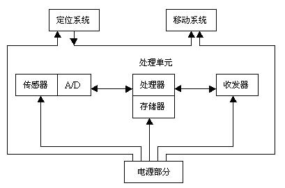
This article refers to the address: http://
Figure 1 Wireless sensor network node structure
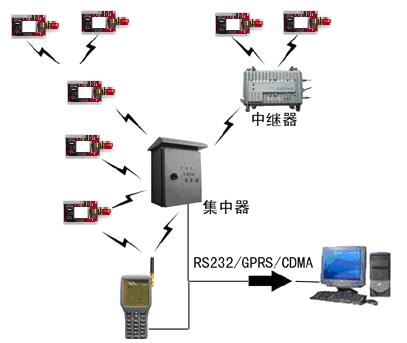
Figure 2 Wireless sensor network node communication topology
SL-SRF-25 ultrasonic sensor, connected to the power supply, can be used as ultrasonic distance measurement alone. The 3-bit LED digital tube displays the obstacle distance. The 3-digit LED digital tube adopts the modular plug-in method, which is convenient for debugging and inspection. occasion. The measurement range is 10cm-250cm. When the distance is less than 100cm, the error is 1~2cm. When it is more than 100cm, the error is 4~5cm. The SL-SRF-25 ultrasonic sensor can also be specified to output a segment distance detection signal from the I/O port of the microcontroller.
3.1.2 Microprocessor Module The processor module selects the Mica2 model node from the University of California, Berkeley. The node board provides the following functions: 433MHz center frequency wireless communication interface, can be customized to customize a variety of functions: can provide -20db~10db multiple communication power; can provide multiple transmissions from 0.3kbps to 38.4kbps in Manchester coding mode Rate; capable of setting multiple communication frequencies around 433M with a frequency interval of 76k. Its high-speed and large-capacity RAM features make it easy to process data packets.
3.1.3 Wireless Transmitter Module The wireless transmitter module adopts the SRWF-501 micropower wireless module RF transceiver from Sangrui Electronic Technology Co., Ltd. The chip requires very few external components, stable performance and low power consumption. The transceiver provides 3 serial ports and 3 interface modes. COM1 is a TTL level UART interface, COM2 is a standard RS-232 interface standard RS-485 interface; crystal frequency stabilization, built-in digital phase-locked loop, frequency according to user needs It can be flexibly set in the range of 300-1000MHz; it automatically filters noise, simplifies the programming of the user interface, and is as convenient as wired; “receives†and “sends†automatic switching, no need for dedicated transceiver control lines, and normal when no data is sent. "Receive" status; automatically convert to "send" status when sending data, automatically return to "receive" after "send"; micro transmit power: maximum transmit power 10mW. The selectivity and sensitivity index of SRWF-501 exceeds the requirements of the IEEE 802.15.4 standard to ensure the effectiveness and reliability of short-range communications.
3.2 System Software Platform Select the TinyOS system development environment developed by the University of California, Berkeley. TinyDB is TinyOS's query processing system that extracts data and information from sensor nodes in a wireless network. TinyOS provides TinyDB with a visual JAVA API window for real-time queries.
3.3 Network Type In this paper, the wireless sensor network adopts a star topology (Figure 2). A network coordinator acts as a central node and can communicate with any common node. The ordinary node contains an ultrasonic sensor to measure and sample the ultrasonic signal strength parameters in the surrounding environment, send the collected data to the central node, and analyze and process the data and commands sent by the central node to complete the corresponding operations. If data is to be transmitted between two common nodes, it must pass through the central node, and the central node transmits the data to the corresponding node.
3.4 Networking Process The wireless sensor network is a self-organizing network. If a full-featured node is activated, it may establish a network and set itself as a network coordinator. Other common nodes can apply to join the network [6]. This makes it possible to build a wireless sensor network with a star topology. The wireless sensor network in this paper supports the superframe structure. After the energy coordinator scans the active channel, the network coordinator periodically transmits the beacon frame according to the set parameters. The ordinary node first obtains the parameters of the network feature, such as the beacon sequence number, the superframe sequence number, and the network label, after the energy scan and the passive channel scan. Synchronize with the network coordinator through a synchronization request, and then associate with the network coordinator through a matching request. In the process associated with the network coordinator, the network coordinator assigns a 16-bit short address [7] to the common node associated with each request. In this way, in the subsequent data transmission, the short address can be used for communication, the communication efficiency is improved, the energy consumption in the transmission is reduced, and the service life of the network is prolonged.
3.5 data transmission mechanism
3.5.1 Data Format Four types of frames are defined in the IEEE 802.15.4 standard, namely beacon frames, data frames, command frames, and acknowledge frames [2].
(1) Beacon frame: used by the network coordinator to broadcast beacons to its neighboring nodes in the first time slot supporting the superframe structure. When a nearby node receives the beacon frame, it can apply to join the network.
Since the wireless sensor network system in this paper adopts a relatively simple star topology, the structure of the beacon frame is different from the IEEE802.15.4 standard: only the source node's network label and short are included in the address field of the beacon frame. Address, does not contain destination node information (because it is sent by broadcast).
(2) Data frame: used to transmit data containing ultrasonic information.
The network label and short address of the source and destination nodes are included in the address field. Since there are two kinds of data frame transmission directions: from the ordinary node to the central node and from the central node to the ordinary node.
(3) Command frame: used to set up a wireless sensor network, transmit synchronous data, and so on. Command frames are not much different in format from other types of frames.
(4) Confirmation frame: used to confirm that the target node successfully received the data frame or command frame. When the target node successfully receives the data frame or command frame, it sends an acknowledgement frame to the sender. The sender receives this acknowledgment frame to indicate that the transmission was successful. If the acknowledgment frame is not received within the specified time, the data frame or command frame is retransmitted.
The type of frame defined in the frame control field is an acknowledgement frame. The sequence number of the confirmation frame is the same as the confirmed frame, and the load length is zero. The acknowledgment frame is followed by the acknowledged frame transmission and does not require the CSMA-CA mechanism to contend for the channel [8].
3.5.2 Transmission Process In the entire wireless sensor network, the ordinary node is used to periodically read the ultrasonic data on its sensor and send the ultrasonic data to the central node. The central node processes the received data and transmits it to the corresponding node to control the vehicle location flag on it. First, the network coordinator checks the received data frame, and the "central node judgment" in Fig. 2 is sensor data for judging whether it is the designated node. If the received data is data on the specified node, the data is compared to an ultrasonic threshold to set a control variable (used to control the switch state of the parking space) [9]. Otherwise, the sending operation is not performed. Then, determine if the node with free joins the network. If a node with an idle is found in the network, the central node sends the control variable as a data frame payload to it. Conversely, data frames with control variables are not sent.
4 Conclusion In our wireless sensor network parking space control system, the ordinary node sends the ultrasonic data it collects to the network coordinator, and the network coordinator sends the data frame containing the control variable to the contact with the parking space duty sign. Ultrasonic data can also be transmitted to the computer via the serial port. The changes in the ultrasonic signal can be monitored by the background software on the computer. The occupancy of the parking space can be judged from the ultrasonic sensor.
This paper discusses the design and implementation of wireless sensor networks from the aspects of wireless transmission protocol formulation and transmission process control. In practice, as long as the specific sensor is replaced, it can be applied to a variety of sensor networks. Because the wireless sensor system has flexible networking and modular design, it has good portability and scalability. With the improvement of people's living standards, this system has broad application prospects in the future traffic monitoring field. In the future of traffic monitoring [10], smart home appliances, the intelligent adjustment of the home environment has broad prospects.
About Silicone Straw :
Straw is common in our life,when we would like to drink some juice,coffe,beer etc,and if you want to elegant to drink it,in this time we can use it.But when we want to drink some hot drinks what can we do it?Yes,use the silicone straw.The temperature at which silicone straw is -40- +240℃ and it is made of food grade silicone.Silicone texture is soft,it is not like stainless steel or plastic that to hurt our mouth.More inportant,the silicone can be reusable and it is be easy to clean.Now,more and more people use silicone straw in all over the world.
Why don't you choose our silicone straw to expend your business?
Silicone Straw introduction:
1.Product name:Silicone Drinking Straw,Food Grade Silicone Straw, Silicone Straw Tips ,Clear Silicone Straw,Silicone Reusable Straw.
2.Place of origin:Guangdong China
3.Color:any pantone color
4.Logo:Printing,debossed,embossed
5.MOQ:500pcs.
6.Package:1 pcs/opp,customized design is available.
7.Design:Customized/stock
8.Certification:FDA,LFGB,SGS,ROHS,etc.
9.Usage:For drinks/Bar accessories.
10.Silicone Straw photo's for reference.

Silicone Straw
Silicone Drinking Straw,Food Grade Silicone Straw,Silicone Straw Tips,Clear Silicone Straw,Silicone Reusable Straw
OK Silicone Gift Co., Ltd. , http://www.oemsiliconegift.com