![<?echo $_SERVER['SERVER_NAME'];?>](/template/twentyseventeen/skin/images/header.jpg)
Abstract: According to the performance characteristics and composition of liquid crystal driver chip HTl621, combined with Freescale microcontroller MC9S08AW32, the design of a home appliance liquid crystal display system is discussed. The practical application of HT1621 in the design of liquid crystal display system is discussed in detail. The hardware structure and software design process of the system are elaborated, and the hardware interface block diagram and software flow chart are given. The liquid crystal display system has excellent performances such as stable display, low power consumption, and friendly interface, and saves resources of the microcontroller I/O port.
Keywords: MC9S08AW32; HT1621; home appliances; liquid crystal display; hardware design; software design
This article refers to the address: http://
0 Introduction The liquid crystal display system is an important part of the home appliance control system. The liquid crystal display system of the home appliance displays important information such as the working state and time through the liquid crystal display module (Liquid Crystal Display), and the user issues an operation command according to the information to the microcontroller for processing, thereby realizing the control of the home appliance function. The liquid crystal display module not only can vividly display graphics, Chinese characters and characters, but also has low power consumption and low working voltage, so it is widely used in modern home appliances. The home appliance liquid crystal display system mainly includes a liquid crystal display module LCD, a backlight, a liquid crystal driving chip HT1621, a Freescale microcontroller MC9S08AW32, and a button module. Here, according to the performance characteristics, composition structure and programming method of HT1621, combined with MC9S08AW32, the practical application of HT1621 in home appliance liquid crystal display system is discussed in detail. The hardware design and software design process of the system are described. The hardware interface block diagram and software flow chart of the system.
1 LCD driver chip HT1621 introduction
1.1 Features of the HT1621 The HTl621 is a 128-segment (32×4) built-in memory multifunction driver from HOLTEK. It can drive multiple segments of LCD characters. The HTl621 can form an LCD display module and display system. It only needs 3 to 4 communication with the microcontroller. It also includes a power saving command, which effectively reduces the power consumption of the system. The HTl621 is a 48-pin SSOP package with many excellent features. The main features are as follows:
(1) Working voltage 2.4~5.2 V;
(2) Embedded 256 kHz RC oscillator;
(3) Power saving commands can be used to reduce power consumption;
(4) A 32 × 4 segment LCD driver;
(5) An embedded 32×4 bit display RAM memory;
(6) Three data access modes.
1.2 HT1621 internal system structure The HT1621 internal system structure includes display memory (RAM), system oscillator, watchdog timer, sound generator and LCD driver. Only the display memory (RAM) and LCD driver associated with this design are described below.
1.2.1 Display Memory (RAM)
The memory RAM is statically displayed, and the displayed data is stored in a 32×4 bit format. The RAM data can be directly mapped to the LCD driver; the data stored in the RAM can be accessed using the READ, WRITE and READ-MODIFY-WRITE commands. Figure 1 is an image from the RAM to the LCD driver.

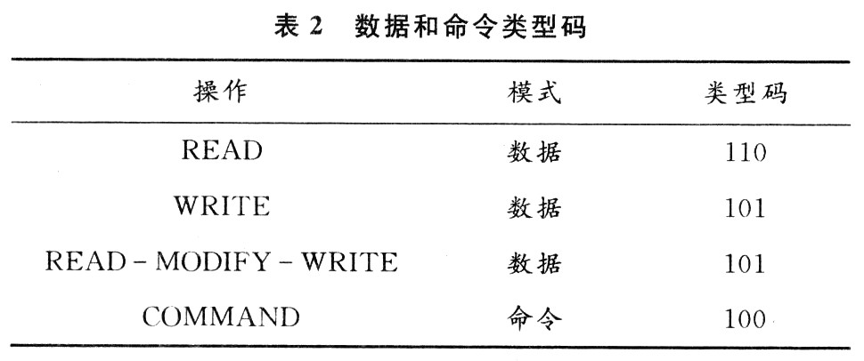
1.2.2 LCD Driver The HT1621 is a 128-segment (32×4) LCD driver. It can be configured by software as a 1/2 or 1/3 LCD driver bias and 2, 3 or 4 common ports. This feature makes the HT1621 suitable for a wide range of LcD applications. The LCD drive clock is generated by the system clock division; the LcD drive clock frequency is maintained at 256 Hz, generated by a 32.768 kHz crystal oscillator, an on-chip Rc oscillator, or an external clock; see Table 1 for LcD driver related commands.

Bold 100 or "100" indicates the command mode type. If a continuous command is executed, the mode type code of the other commands will be ignored except for the first command. The LCDOFF command disables the LCD bias generator, thereby turning off the LCD display; the LCD ON command activates the LCD bias generator to turn on the LCD display. BIAS&COM is an LCD module related command that makes the HT1621 compatible with most LCD modules.
1.3 HTl621 Command Format The HT1621 can be set in software. Two modes of commands can be configured to configure the HTl621 and transmit the data displayed by the LCD. The configuration mode of the HTl621 is called command mode, and the command mode type code is 100. The command mode includes a system configuration command, a system frequency selection command, an LCD configuration command, a sound frequency selection command, a timer/WDT setting command, and an operation command.
The data mode includes READ, wRITE and READ-MODI-FY-WRITE operations, and Table 2 is the data and command mode type code table. Mode commands should be run before data or commands are transmitted. If a continuous command is executed, the command mode code is 100 and will be ignored. When the system is in discontinuous command mode or discontinuous address data mode, port CS should be set to "1" and the previous operating mode will be reset. When port CS returns "0", the new operating mode type code should be run first.
2 Design of hardware circuit of liquid crystal display system
2.1 MC9S08AW32 Microcontroller The MC9S08Aw32 microcontroller is one of the members of the high-performance HCS08 core based on Freescale Semiconductor. It contains many valuable features such as 20 MHz internal bus frequency, 32 KB on-chip programmable FLASH memory, 2 KB on-chip RAM, flexible internal clock generator without external components, low-voltage detection, high-performance analog-to-digital conversion (ADC), serial communication module, etc. The MC9S08Aw32 achieves excellent EMC performance even in all kinds of harsh environments.
2.2 hardware interface circuit The hardware interface circuit of the liquid crystal display system mainly includes the microcontroller MC9S08Aw32, the liquid crystal display module LCD, the backlight, the liquid crystal driver chip HT1621 and the button module, and the resistors and capacitor components, as shown in Figure 1.
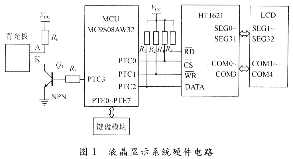
In FIG. 1, the PTC0~PTC2 ports of the microcontroller Mc9S08AW32 are respectively connected to the chip select signal port (CS), the "write" signal control port (WR) and the data signal port (DATA) of the liquid crystal drive chip HT1621, and are respectively connected. Pull the resistor to a high level (Vcc). Since there is no need to "read" the HT1621, the "read" signal control port (RD) simply needs to be tied high (Vcc) through a pull-up resistor. M (the PTE0~PTE7 port of the 29S08AW32 is connected to the keyboard module; the PTC3 port is connected to the NPN transistor to control the backlight board. The COM0~COM3 ports of the liquid crystal driver chip HT1621 are respectively connected to the COM1~cOM4 ports of the LCD; the SEGO~SEG31 ports are respectively connected with the LCD The SEG1~SEG32 ports are connected. When the number of display segments of the LCD is less than 128 (32×4), the remaining drive ports of the HT1621 are blanked. The LCD used in the design has 4 common ports and 32×4 segment codes.
3 Software implementation of liquid crystal display system Microcontroller MC9S08AW32 is connected with "CS", "WR" and "DATA" of HTl621 through three ports, PTC0PTC2, to realize the control of "write" command and data of liquid crystal driver chip. “CS†is the chip select signal terminal VI of the HT1621. When “CS†is low and as an input, the “read/write†data and commands of the HT1621 are valid. "DATA" is a serial data input/output port, and "read/write" data and "write" commands are performed by "DATA". “WR†is the write clock input port. When the “WR†signal is the E rising edge, the data address and command on the terminal “DATA†are written to the corresponding RAM area on the HT1621. During the initialization of the microcontroller, set PTE0 to PTE7 as input ports. The MC9S08AW32 detects and judges whether a button is pressed by scanning the status of these ports, and performs a "write" operation on the HT1621 through the MC9S08AW32 to display the corresponding function on the LCD. At the same time, when a button is pressed, the MC9S08AW32 outputs a high level through the PTC3 port, the NPN transistor Q1 is turned on, and the backlight K pole is pulled low. When there is no key operation for a certain period of time, the backlight is turned off to reduce power consumption. Through programming, when there is a button operation, the LCD can flash to display the working mode of the user to select the home appliance. If there is no button operation, the LCD displays the current time, working status and other information.
3.1 HTl621 initialization and control timing HTl621 is a programmable chip. According to the command and data code of HT1621, the initialization of HT1621 and the setting of the mode related to "write" data and commands are completed by "writing" the following macro definition program to HT1621.
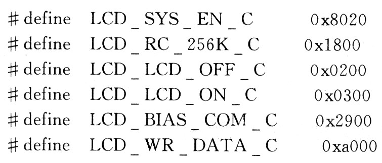
Figure 2 shows the signal timing diagram for the “write†command and data for the HT1621.

According to the signal timing diagram of the "write" command and data in Figure 2, and the port definition of the MC9S08AW32, the MC9S08AW32 initializes the three control ports of the HTl621 as "output" through the following assignment statement and macro definition, completing the high and low levels of the three ports. set up. 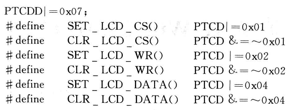
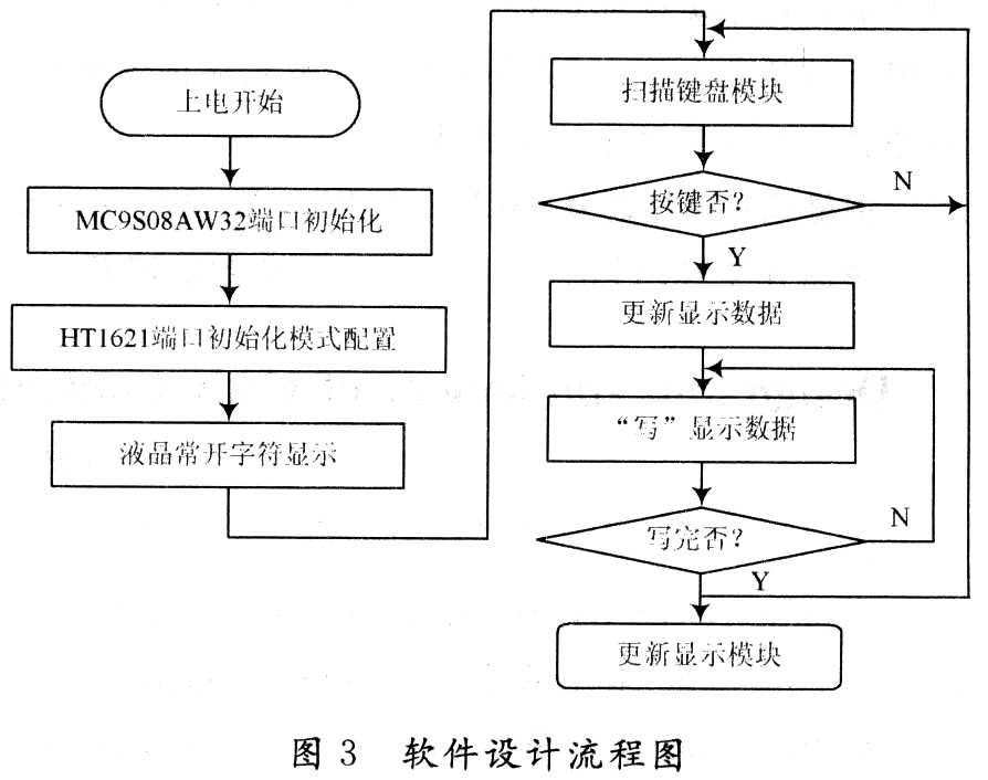
3.2 Software Design Flow Chart The software design flow chart is shown in Figure 3.
4 Conclusion This design is mainly used in the display part of the home appliance control system. The liquid crystal display system is an important part of the home appliance control system. Both the MC9S08AW32 and HT1621 offer high performance, low power consumption, and high reliability. At present, the combination of the two has been successfully applied to liquid crystal display systems for household appliances such as rice cookers, refrigerators, air conditioners, and washing machines. Practice has proved that the display system not only shows stable stability, low power consumption, convenient design and use, but also reduces the production cost by saving the single-chip I/O port, and meets the requirements of the industrial display system performance.
Power Bank OEM,Phone Power Bank ,Powerbank ,Portable Power Bank
LED light Co., Ltd. , http://www.nbpcbassembly.com