![<?echo $_SERVER['SERVER_NAME'];?>](/template/twentyseventeen/skin/images/header.jpg)
1 Introduction
This article refers to the address: http://
This design is designed to participate in the electronic design competition, which better solves the problem of operation and control of the electric vehicle on the seesaw. The system structure is relatively simple and the control is relatively accurate.
2. System design, comparison and demonstration
According to the basic requirements of the topic, the design task mainly completes the electric vehicle to run stably according to the prescribed path within the specified time, and can have the function of maintaining balance, and simultaneously process and display the relevant data in the stroke. In order to complete the corresponding functions, the system can be divided into the following basic modules: motor drive module, trace detection
Module, balance state detection module, information display module. see picture 1
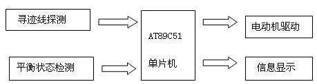
Figure 1 system block diagram
2.1 tracing line detection module
The principle of detecting the black trace line on the road surface: the light hits the road surface and reflects. Because the reflection coefficient of the black line and the white paper are different, the high and low levels can be generated by the sensor according to the intensity of the received reflected light, and finally the black line is judged by the single chip. Or deviate from the runway.
Solution 1: A transmitting-receiving circuit composed of a visible light emitting diode and a photodiode, as shown in FIG. 2 . The solution is low in cost and easy to manufacture, but its disadvantage is that the surrounding ambient light source will greatly interfere with the operation of the photodiode. Once the external bright conditions change, it is likely to cause misjudgment and missed judgment; if super bright fluorescent tubes are used and High-sensitivity phototubes reduce some interference but add extra power loss.
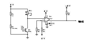
Figure 2 Scheme 1 circuit
Option 2: Homemade infrared probe circuit. This method is simple, inexpensive, and adjustable in sensitivity, but is susceptible to the surrounding environment, especially the influence of strong illumination on the detection signal, which may cause system instability. again
Coupled with limited time, making discrete circuits is cumbersome.
Option 3: Integrated infrared probe. An integrated intermittent photoelectric switch detector can be used, which has the advantages of high integration and reliable performance. The sensitivity of the probe can be controlled by simply adjusting one knob on the probe. This type of probe also effectively prevents interference from ordinary light sources such as fluorescent lamps. The infrared detector E3F-DS30C4 is shown in Figure 3.
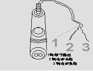
Figure 3 integrated infrared probe
Based on the above considerations, in order to improve the accuracy of system signal acquisition and detection, we adopt scheme three.
2.2 Balance state detection module
Solution 1: Intermittent photoelectric switch. One is placed on the ground at both ends of the seesaw, and the sensitivity is adjusted so that the reflected light is not generated within a certain range to generate a low level, so that the equilibrium state is considered, and the movement state of the trolley is controlled by the single-chip microcomputer to achieve dynamic balance of the seesaw. However, the balance control of this scheme is not sensitive and difficult to adjust. It is also necessary to use a wire and a single chip to transmit signals, so that the car loses its independence.
Option 2: Use an angle sensor. The integrated chip is a dedicated horizontal inclination measuring chip, which has the advantages of small volume, high sensitivity, simplicity, reliability, etc., and can highly satisfy the precise requirement of the balance angle of the problem.
After comparing the above two schemes, scheme 2 is obviously superior to scheme one, so scheme 2 is adopted.
2.3 Selection of motor and its drive module
According to the time requirement of the whole car driving in the title, it can be seen that the driving speed of the car is very slow, and the ordinary motor is difficult to meet the speed requirement, and the DC gear motor can meet this requirement, and has a large rotating torque and does not be on the inclined surface. A stall situation has occurred. Therefore, we use DC geared motors.
There are two options for selecting a driver module: one is to use a dedicated driver chip. The chip has high integration degree and small footprint, and is mainly used in motor speed regulation occasions, but the price is high. The second is to use a transistor drive circuit. Since the functions required for electric vehicles are relatively simple, it is possible to drive them with a crystal triode, so we finally decided to use the second scheme.
2.4 Information Display Module
If LED is used, the disadvantage is that it occupies too many interfaces of the MCU, displays less information, needs to be displayed cyclically, and takes up too much program resources. The use of LCD, only occupy 6 I / O lines of the microcontroller, while displaying a large amount of information, flexible display a variety of information. Therefore, we intend to adopt the latter.
2.5 Power supply selection
Solution 1: All devices use a single power supply (5 AA batteries). This kind of power supply is relatively simple, but because the motor starts to have a large current, it will cause voltage instability, glitch and other interference. In severe cases, the microcontroller system may be powered down, making it impossible to complete the scheduled trip.
Option 2: Dual power supply. The motor drive power supply adopts 5 sections of 5th battery (large capacity 2.3Ah battery), and the single-chip microcomputer and its peripheral circuit power supply are powered by another group of 3 5th batteries (large capacity 2.3Ah battery), and the two power supplies are completely separated. It is not as convenient and flexible as a single power supply, but it can completely eliminate the interference caused by the motor drive and improve the stability of the system.
We believe that the stability and reliability of this design is more important, so we plan to adopt Option 2.
After a careful demonstration, the block diagram of the electric vehicle slab system that we finally determined is shown in Figure 4.
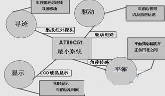
Figure 4 Electric vehicle seesaw system block diagram
3. System discrete module design and working principle
3.1 tracking line detection circuit
The model is E3F-DS30C4 integrated intermittent photoelectric switch detector, the probe output only has three wires (power line, ground line, signal line), as long as the signal line is connected to the I/O port of the microcontroller, and then keeps on The I/O port is scanned and detected, when it is at a high level, white paper is detected, and when it is low, a black line region is detected. When the car advances (reverses), always keep the black line between the two sensors at the front (the rear). When the car deviates from the black line, once the detector detects a black line, the MCU will send the command according to the pre-programmed procedure. To the control system of the car, the control system then corrects the car path. When the car returns to the track, the two detectors in the front (the rear of the car) only detect the white paper, then the car continues to walk straight, otherwise the car will continue to adjust the direction until the car returns to normal.
3.2 Balance state detection circuit
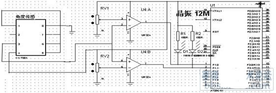
Figure 5 partial pressure comparison type balance detection circuit
In the balance detection circuit, we use a high-precision angle sensor, which measures the voltage value within a certain range corresponding to the linear output by measuring the deviation from the horizontal angle. According to the requirements of the topic, we analyzed that the car is considered to be in equilibrium when the amplitude of the on-board swing is at plus or minus 4 degrees. The angle sensor has the highest sensitivity in this interval, and its output voltage is between 2.45 and 2.55 volts. The output voltage is amplified by comparison, and then converted into a digital quantity by the A/D converter and passed into the single chip microcomputer. However, since the entire range of variation is only 0.1 degree, any slight interference will cause serious deviations in the measurement results. Using A/D conversion will reduce the accuracy, the interference is too large, and because it is difficult to achieve true static balance in reality, we finally decided to adopt dynamic search for balance, so we use voltage divider circuit and voltage comparator to make signal. The circuit controls the car according to the change of the signal end, so that the voltage output of the angle sensor is maintained between 2.45 and 2.55 volts. After many tests and careful debugging, the circuit can meet the requirements well. The balance detection circuit is shown in Figure 5.
3.3 Motor drive circuit
The motor drive circuit is shown in Figure 6. J1 in the drive circuit is connected to the motor, and MOT1 and MOT2 are connected to the high and low levels to control the forward and reverse rotation of the motor, thereby controlling the forward and reverse of the motor and the left and right steering.
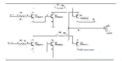
Figure 6 motor drive circuit
4. Software design
The software structure is shown in Figure 7. (Detailed software flow chart see Appendix)
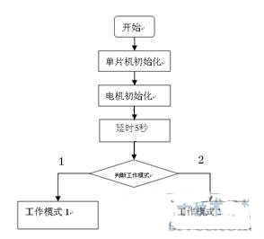
Figure 7 software structure
When the system is turned on, the system is reset, and then the system determines the working mode. When the working mode 1 or the working mode 2 is selected, the system waits for 5 seconds and then enters the automatic timing running state.
Mode 1 is an electric vehicle running and direction adjustment program, which makes the electric vehicle run according to a predetermined route, and automatically adjusts the direction after the trolley deviates from the track to automatically return the trolley to the predetermined route, and controls the LCD to display the running time in real time. Mode 2 is the balance detection and balance hold program. Under this program control, the car automatically finds the balance point and performs forward or reverse operation near the balance point to finally achieve dynamic balance.
5. System testing
5.1 Test equipment
Homemade fascia board: length 1600mm, width 300mm, the distance between the bottom of the raft board and the ground is 70mm. The middle picture has a 50mm wide black trace.
Tape measure: accuracy 1mm.
Stopwatch: Accuracy 0.01s, two pieces.
5.2 Test results and analysis
5.2.1 When the horizontal state of the seesaw is measured, the time of the round trip is measured. The test data is shown in Table 1:
Table 1 Seesaw level status detection data
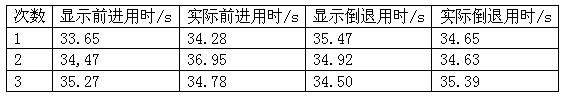
Analysis: The actual measured time is different from the display time, which may be the human reaction time error.
5.2.2 Measure the time of the round trip once in the free state of the seesaw. The test data is shown in Table 2:
Table 2 Round trip time detection
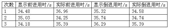
Analysis is the same as above.
5.2.3 The car is kept in balance test under the free state of the seesaw. (with a weight of 200 grams) The test results are shown in Table 3:
Table 3 Seesaw balance test
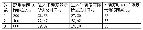
Analysis: From the above data, the total time required for the system to enter the equilibrium state gradually decreases as the distance of the weight from the A end increases, while the maximum amplitude of the equilibrium state is basically unchanged. This is because the weights are close to the center, the torque for the fulcrum is continuously reduced, and the inertia is also reduced, resulting in a gradual decrease in the total time required for the equilibrium state.
5.2.4 Pressure line positioning test. The test data is as follows:
Table 4 è··è·· plate pressure line positioning test
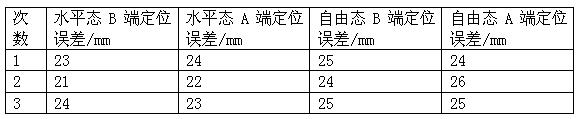
Analysis: Most of the first two probes that are positioned in the direction of the car are pressed into the line to stop. In rare cases (when the tracking line has a large camber), the probe in front of the car has not been touched. The line will stop even when it starts to run. Observe the reason of the phenomenon analysis. When the tracking line has a large curvature and the car can not effectively correct the excessive deviation, the two probes in front may detect the black tracking line at the same time, so that the car stops.
The test results show that the design successfully achieves the requirements of the topic and has good use value.
references
[1] National College Student Electronic Design Competition Organizing Committee, "Collection of Award-winning Works of National Undergraduate Electronic Design Competition" [M]. Beijing Institute of Technology Press. 2006
[2] Wu Shaojun, Liu Guangbin. "Microcomputer Practical Low Power Design" [M]. People's Posts and Telecommunications Press. 2005
[3] Zhou Hangci. "Single-chip application programming" [M]. Beijing University of Aeronautics and Astronautics Press. 2006
[4] Gao Jixiang. "National College Student Electronic Design Competition Training Course" [M]. Analog Electronic Circuit Design. 2007. Chapter IX
[5] Huang Zhengwei. "Electronic Design Competition Competition Analysis" [M]. Southeast University Press. 2003. Chapter V
[6] He Limin. "Single-chip application programming design technology" [M]. Beijing University of Aeronautics and Astronautics Press. 2003. Chapter 2.
[7] Tong Shibai, Hua Chengying. "The Foundation of Analog Electronic Technology" [M]. Higher Education Press. 2000. Chapter 6.
[8] Li Chaoqing. "Single-chip microcomputer principle and interface technology" [M]. Beijing University of Aeronautics and Astronautics Press. 2005. Chapter 4.
Digital currency transactions allow users to convert existing digital currencies into other digital currencies. The entire transaction does not involve any legal tender. Because of the relatively loose regulation, the mainstream digital currency trading platform also opened this function.Digital Asset Exchange (DAE) is a platform for matching transactions between digital currencies, digital currencies and legal currencies. It is the main place for encrypting the circulation and price determination of digital currency transactions.
Compared with traditional stock exchanges, digital asset trading platform not only matches transactions, but also plays the role of market maker and investment bank. The role of the market maker in the trading platform can increase the liquidity of the market, and the trading platform can earn the transaction price difference. The role of the investment bank of the trading platform is to provide services such as issuance and underwriting of digital currency, from which the trading platform collects money fees, or collects deposits in the form of community voting of the trading platform.
Currency Exchange,Digital Currency Exchange,Virtual Digital Currency Exchange,Display Currency Exchange
China youbi digital assets limited , https://www.ubcoinchina.com