![<?echo $_SERVER['SERVER_NAME'];?>](/template/twentyseventeen/skin/images/header.jpg)
Tag: ST40GX1 STi5514
This article refers to the address: http://
From the perspective of hardware development, interactive set-top boxes and digital TVs have evolved from early discrete devices to modern single-chip solutions. This is the result of technological advances in digital LSI manufacturing processes and an inevitable requirement to minimize system cost. Set-top boxes for modern single-chip solutions typically integrate modules such as CPU, demultiplexing, audio and video decoding, 2D graphics processing, encoding, and peripheral ports. To save chip area, these separate parts are connected by bus. Improving the performance of the system usually starts with improving the speed of the CPU, enhancing the processing capability of the two-dimensional or three-dimensional graphics, increasing the number and class of interfaces of the peripheral ports, and thus improving the interactive processing capability of the system as a whole. However, since the video demultiplexer and the audio video decoder have strict requirements on real-time access to the data bus, the CPU processing waiting time is increased, and a so-called bus bottleneck is formed. Tests have shown that the bus bottleneck causes the CPU to execute instructions up to 76%. This simple improvement of CPU performance to overcome the lack of processing power does not improve the price/performance ratio. Improving bus bottlenecks can be done by improving or adding system interconnect buses, such as Panasonic's Cross Switch solution, which reduces latency to 50%. But these will certainly increase the complexity of interconnects in chip manufacturing, thereby increasing costs.
In addition to the problems caused by the bus bottleneck, with the increasing diversity of access methods and graphics and image processing requirements, the interactive set-top box backed by the telephone line, the narrowband access method of digital TV and limited computing power are also More and more unable to meet people's requirements. With the two-way transformation of the wired HFC network and the acceleration of its integration with the telecommunications network and the Internet, the user can add flexible and optional broadband access methods such as Cable Modemî—¤CM and Ethernet, and add advanced 2D and even 3D advanced graphics. Processing becomes an important aspect of set-top box applications.
1 Dual CPU solution based on ST40GX1 and STi5514
To solve the above problem, ST Microelectronics recently selected a dual processor solution based on the STi5514 single-chip decoder and the ST40GX1 two-dimensional graphics processor. This solution avoids the bus congestion caused by the multiplication of peripheral modules and the latency of decoding real-time requirements. The STi5514 and ST40GX1 are internally interconnected using high-speed advanced STBus. The former is responsible for real-time requirements for hardware demultiplexing, video and audio decoding, and peripheral I/O device control associated with decoding. The latter is responsible for broadband interactive applications as well as advanced graphics processing. The high-speed data communication between the two is performed through the MPX (Memory Peripheral Exchange) bus and the storage mapped mailbox (Mailbox). With a 100MHz MPX bus, the STi5514 can directly access up to 256MB of DDR SDRAM memory on the ST40GX1.
1.1 STi5514 features and interfaces
The STi5514 mainly performs decompression of MPEG-2 video and audio signals. It integrates a MP@ML standard definition video decoding module and a Dolby AC-3/AAC/DTS audio decoding module as well as Video Encoder and Audio DAC modules. The internal 32-bit RISC CPU works at a frequency of 120MHz. Under the external V.90 hardware Modem, it can be used for narrowband interactive applications over the telephone line, such as video on demand based on telephone line backhaul, low-speed Internet browsing.
Compared with ST's earlier single-chip decoder STi5512, the outstanding features of the STi5512 are: the instruction and data buffer are doubled, and the three-way TS (Transport Stream) stream input is concurrently processed. Multiple descrambling modes (including DVB, DES, ICM, Fast-I), directly support Dolby AC-3/AAC/DTS audio decoding, provide ATAPI hard disk circuit interface, and directly support Ultra-DMA66 high-speed data transfer mode hard disk In order to realize real-time recording of digital TV programs, the video decoding stream can be outputted in ITU-R601_656 format data stream or in different analog modes such as composite video signal î—¤CVBS î—¥, component signals RGB and YUV, support Teletext decoding output, and provide two pairs. The SIM card interface facilitates the expansion of advanced applications such as bank cards. Since the STi5514 removes the 1394 interface, an external 1394 controller (such as STE422) is required to extend the 1394-based video input.
1.2 ST40GX1 features and structure
The ST40GX1 integrates the SH-4 32-bit RISC processor core, Gamma 2D image processing, hybrid modules, and other video circuit interface logic.
The ST40GX1 is the processing core of interactive applications, including system equipment and peripherals.
1.2.1 System equipment
The ST40GX1 system equipment includes a central processing unit CPU, a floating point arithmetic unit/addition processing unit (FPU/Mac) for DSP functions, a memory management unit (MMU), and a DMA control module.
Among them, the CPU is a 32-bit SuperH RISC, 2-channel superscalar architecture, 166MHz, 16-bit instruction fixed-length Load-Store structure, 8KB direct instruction cache, 16KB direct operand cache, with an on-chip multiplier.
The memory supports 4G of storage space and supports single or multiple virtual memory modes. The page size can be 1KB, 4KB, 64KB or 1MB. Supports 4-channel full correlation instruction ITLB (Instruction Translation Lookaside Buffer), 64-channel fully correlated instruction, and operand UTLB. Supports software-controlled update algorithms and random count update algorithms. This provides a complete hardware platform for the operating system in 32-bit protected mode.
The general-purpose DMA controller supports five channels of data transfer, four of which can be used for memory-to-memory or memory-to-peripheral data transfers, and the other is a buffered multi-way composite channel. Supports the movement of 2D blocks and linked list operations. Two channel DMA handshake signals and EMI interface signals are used for MPX bus operation.
1.2.2 Peripheral Interface Module
The peripheral interface module includes a universal interface module and a video dedicated interface module.
The Universal Interface Module includes two full-duplex asynchronous serial communication ports compatible with the ST40 family of processors, an interrupt controller, an IEEE1149 compliant debug controller, a real-time clock, four user-programmable PLLs, and 24-bit input and output directions. Configurable parallel I/O port, two USB host controllers and transceivers conforming to the v1.1 specification, Modem analog front end interface MAFE, two synchronous serial controllers configurable to support I2C or SPI bus interface standards ( SSC0î–„SSC1), Teletext input interface, two SmartCard interfaces using asynchronous protocol, storage mapped mailbox (Mailbox) for communication with external microprocessor, PCI interface controller conforming to PCI2.1 specification, two audio PCM input Interface and one PCM output interface.
The video-specific interface and processing module includes a word video input port and a 2D image processor.
Two CCIR601-656 video input ports (DVP0, DVP1) can simultaneously input video data in YCbCr 4:2:2 format and load it into local memory. The video without the embedded sync signal also provides external sync signal support according to the SAV/EAV protocol. The user can set the video capture window and the sub-window of the active window from the input video image. The Digital Encoder (DENC) converts the digital video stream into a standard analog baseband PAL/SECAM/NTSC signal and RGB and YUV analog component signals. If 32-bit DRAM is used on the LMI, a RGB 24-bit digital video stream can be obtained. The 2D image processor (or image block transfer engine) has two 2D DMA image data input sources for a complete set of powerful processing operations. In addition to the normal 2D graphics acceleration function, it can also convert between different graphics formats (RGB/YUV, etc.), including block filling, block copying, asynchronous composite, color conversion and 2D scaling processing.
2 System structure based on STi5514 and ST40GX1
The overall structure of the system proposed according to the functional characteristics of STi5514 and ST40GX1 is shown in Figure 1.
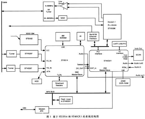
2.1 front end decoding part
Since the STi5514 has three TS stream descrambling channels built in, the dual channel Turner+STV0297QAM demodulator is used to simultaneously demodulate the DVB-C based video data transmission stream of two channels. Taking full advantage of the STi5514's hardware descrambling, control processing and decoding capabilities, you can achieve picture-in-picture functionality. Among them, Turner can use MicroTune's MT2040 single-chip tuner to save space and cost. In addition, IEEE 1394 interface input is supported by an external STE422.
2.2 Backend decoding part
The backend decoding is done by the STi5514. The STi5514 completes the memory resources required for channel demodulation, demultiplexing, and decoding through an external 8MB shared SDRAM. The STi5514 shares 16MB of FLASH on the ST40GX1 EMI interface via the MPX bus. Extend the VCR application by external hard disk storage through the ATA interface. The STi5514 decoded video data conforming to the ITU-R601_656 standard is directly input to the DVP0 of the two video input ports of the ST40GX1 through the video output port. The STi5514 sends a 27MHz pixel clock and sync signal to the ST40GX1 to ensure proper reception of the STi5514 video data.
2.3 Graphics processing and network interface for interactive applications
The interactive application hardware implementation is partially done by the ST40GX1 and the corresponding network interface.
2.3.1 ST40GX1 two-dimensional graphics processing
The ST40GX1 receives the decoded video stream input from the STi5514, and after interpolation and color space coordinate transformation, it performs complex processing such as alpha blending and gamma processing on other video streams such as web browsing to form a unified video. The frame buffers the data and encodes it into an output of the composite video signal CVBS, SVideo or component signals RGB, YUV, etc., which can be processed by the analog TV through the internal DENC.
Because the ST40GX1 only supports the 3.3V PCI interface, it can expand the 3.3V or 5V PCI slot through Intel's SB21150BC. In the case of 3D image processing, the PCI 3D graphics accelerator card can be externally implemented.
2.3.2 Network Interface
Taking into account the broadband access method requirements of the network interface, the ST40GX1 is used to integrate the PCI bus interface provided externally, and integrates high-speed interfaces such as Cable Modem and Ethernet.
2.3.2.1 Cable Modem
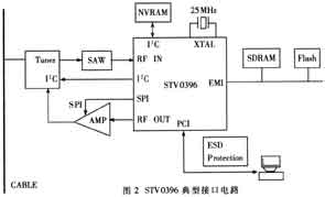
The Cable Modem front-end single-chip interface chip STV0396 conforming to the Docsis1.1/Euro-docsis1.1 specification is selected as the Cable Modem solution. This part can be designed as a stand-alone PCI card or directly embedded on the motherboard. The STV0396 is a highly integrated modem system that includes support for upstream and downstream DOCSIS 1.1 compliant physical layer specification interfaces, Media Access Control (MAC) and powerful 32-bit ST20 RISC processors, PCI, EMI/MPX Wait for an external interface compatible with the ST40GX1. The STV0396 is packaged in a 316-pin BGA package. In addition to the external bidirectional tuner, it is necessary to add a surface acoustic wave filter î—¤SAW î—¥, a line amplifier in the upstream direction, and a clock to achieve the cable head end device. Communication connection between CMTS. Its typical interface circuit is shown in Figure 2.
2.3.2.2 Ethernet interface
The RTL8139C-based 3.3V Ethernet chipset is selected as the interface chip, mainly considering that the chip is highly integrated, widely used in embedded systems, and 10/100M adaptive features, its own PCI interface, and driver under Linux-like operating system. The program is easy to find and other advantages. The RTL8139 is available in a 128-pin QPF/LQPF package and is connected to the ST40GX1 via a PCI bus interface.
2.3.2.3 V.90 Software Modem Support
Support for the V.90 software Modem is directly implemented by using the ST40 front-end interface MAFE of the ST40GX1. Not using the hardware modem is to take full advantage of the ST40GX1's processing power to reduce costs.
2.4 Startup and communication
The ST40GX1 and STi5514 determine the system startup sequence by configuring the master/slave (initiator/target) mode of the respective MPX bus interface. Here, since the system startup code is located in the local FLASH of the ST40GX1, the ST40GX1 is configured as an Initiator, and the STi5514 is configured as a (Target). The specific boot sequence is: ST40GX1 first controls the MPX bus and starts first, preventing the STi5514 from using the MPX bus during startup until it completely reads the boot code and initialization from Flash. The ST40GX1 then uses the MPX bus to copy the STi5514 bootloader and application code into its own LMI DDR memory. After the copy is complete, the ST40GX1 releases and allows the STi5514 to control the MPX bus. The STi5514 copies its own bootloader and application code from the ST40GX1's DDR SDRAM. Drawing on this, storage sharing between multiple CPUs can be achieved through the MPX bus.
The STi5514 has access to the Mailbox registers on the ST40GX1 via the MPX bus. The Mailbox is fixedly mapped to the base address 0x1B150000 of the ST40GX1 memory space. This register can generate an interrupt signal for both CPUs. Through the Mailbox register, ST40GX1 and STi5514 can realize process synchronization such as process synchronization and message transmission.
This paper introduces in more detail the system composition and implementation of high performance network interactive digital TV set-top box based on ST40GX1 and STi5514. Although the low-end basic pay/free digital TV set-top box will become a consumer choice for a long time, as the user's demand for functions increases and the cable operator's service content is rich, the number of such high-end applications is provided to users. TV set-top boxes will also find an increasingly widespread application.
Economical Channel type fiberglass flexible Cable support tray Application
- Frp Cable Tray is Universally used in petroleum industry, chemical industry, electronic plant
- FRP Cable Tray is Suitable for some environment with high corrosion
- Modern factories and buildings with high floors
-
Any environment that need to be closed
Economical Channel type fiberglass flexible Cable support tray:
FRP cable tray is consists of a ventilated or solid bottom contained within longitudinal side members. Provides moderate ventilation with added cable support frequency and with the bottom configuration providing cable support every 4 inches. Available in metal and nonmetallic materials. Generally used with control and instrumentation cables in moderate heat generating applications with short to intermediate support spans of 5 feet to 12 feet. FRP cable tray bottom is available in flat sheet or corrugation that is 3 times stronger and 21 times stiffer than flat sheet bottoms. Corrugated seams between jointing sections eliminate need for bottom seam splices. Load Depths: 3" through 5-1/2" Materials available: Aluminum, hot-dipped galvanized Steel,Stainless Steel or figerglass.
Outdoor Cable Tray,C Channel Cable Tray,Aluminum Alloy C Channel Tray,Channel Type Cable Tray
Jiangsu Loncin Electric Equipment Co.,Ltd , https://www.loncincabletray.com