![<?echo $_SERVER['SERVER_NAME'];?>](/template/twentyseventeen/skin/images/header.jpg)
Application and Fault Analysis of PWM Circuit Designed by TL594 in High Frequency Machine
With the development of technology, traditional X-ray machines are gradually being eliminated by the market, and high-frequency machines are gradually going to the market. To this end, this article mainly introduces a comprehensive use circuit based on TL594 pulse width modulator and high frequency inverter technology, as well as related fault phenomena and troubleshooting ideas. In fact, no matter whether it is Siemens, GE, Shimadzu, or Neusoft, Wandong, Shangji Factory and other related equipment in the world, no specific circuit manual is provided for various purposes. As a staff member of a teaching and maintenance organization, in the course of work, the author has repeatedly made blind replacements because he does not understand its complete working principle, which is time-consuming and laborious. As a guide, this article focuses on the related circuit working principle and the cause of failure of the HF50R film machine produced by Wandong. The basic concept of this machine is very similar to the early products of Spain.
HF50R as a domestic high-frequency machine, although some of its hard indicators still can not meet the higher requirements, such as the ball tube still uses non-high-speed tube, the high-voltage inverter frequency (25 kHz) is still less than the required 30kHz condition (current international high-frequency has Can reach more than 100 kHz), but its basic working concept has been in line with international standards. The high-voltage inverter electronic switch also uses the insulated gate bipolar transistor (IGBT) currently used internationally. The filament inverter electronic switch uses the IFR540 transistor, and its driving signals are all from the PWM circuit composed of TL594.
1 Introduction to TL594
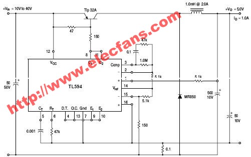
TL594 application circuit
1.1 Internal composition of TL594
TL594 consists of a reference voltage generation circuit (Reference Regulayor), a rectangular wave oscillator (Oscillator), two error amplifiers (Error Amp), a dead time comparator (DeadTIme comparator), a pulse width modulation comparator (PWM comparator) and related outputs Circuit composition.
1.2 Pin function of TL594
The functions of each pin of TL594 are as follows:
1, 2 feet: the same direction, reverse input end of a group of error amplifiers;
16, 15 feet: the same direction, reverse input terminal of another group of error amplifiers;
3 feet: the output end of two groups of error amplifiers;
14 feet: 5 V power supply terminal, used as the reference voltage value source of each comparator circuit, the maximum withstand current of this foot is 10 mA;
7 feet: GND;
13 feet: working mode selection end. If pins 13 and 14 are connected, the two tubes are push-pull outputs, and the load current can reach 500mA at this time;
6 feet (RT), 5 feet (CT): the frequency setting end of the oscillator, its frequency is: fosc = 1.1 / RTCT.
4 feet: dead time setting pin. The voltage range at this point is 0 to 3.3 V. (This unit is 1.0 V)
12 feet: 7 ~ 41 V power supply (12 V of this machine).
9, 10 feet: The output end can output pulses with a phase difference of 180 °.
1.3 The basic working principle of TL594
Under normal circumstances, the flip-flop (FLIP-FLOF) clock signal will be gated when it is low, and this signal is controlled by the OR gate, and its control signals are from the dead zone comparator, PWM comparator, and under Press lock comparator. The positive sawtooth output from the oscillator is added to the inverting input of the dead zone comparator and the PWM comparator, respectively. The dead zone control voltage has an input compensation voltage of 0.12 V, which limits the dead zone time to at least greater than 4% of the sawtooth wave period, that is, the maximum output duty cycle (Duty cycle) is 96%. The input signal of the PWM comparator of TL594 comes from the synthesis of the output terminals of two sets of error amplifiers and the feedback signal. In this way, when the sawtooth wave signal is higher than the control signal, the OR gate outputs a low level, the flip-flop is gated, Q1, Q2 will get the excitation signal and output a pulse signal whose pulse width varies with the level of the control signal.
TL594 has a built-in 5 V reference power supply. The temperature drift in the range of 0 ~ 70 ℃ is less than 50 mV, and the voltage can reach ± ​​1.5% accuracy.
2 HF50R PWM circuit
The PWM circuit of HF50R high-frequency machine is mainly used in kV and mA adjustment board. The driving signal of the focus filament circuit in the mA adjustment board is respectively completed by two PWM circuits.
2.1 The filament principle of HF50R
The PWM circuit of the filament adjustment board (take small focus as an example) RT = 11 K, CT = 0.01μF, from which the oscillator frequency can be calculated as 10 kHz. The dead zone voltage is adjusted and sampled to 1.0 ± 0.3 V by the built-in 5 V power supply through VR3. Pin 2 is the FILAlSET (filament setting) signal from the CPU, pin 1 is the primary sampling signal of the filament, and its output signal can control the pulse width. The inverting input terminal (pin 15) of another set of error amplifiers of TL594 is +5 V power supply, and pin 16 is the potential after comparing the primary sampling signal of the filament with the reference voltage set by R54, if the sampling signal is less than 2.0 V. Then TL594 can work normally (in the large focus drive circuit, the maximum sampling signal is set to 2.5 V by R74). According to the size of the tube current selected by the console, the PU will send the corresponding filament setting signal, and the sampling signal is also sent to the same-direction input terminal of the error amplifier to change the 3-pin potential according to the difference between the setting signal and the sampling signal. High and low, so as to achieve the purpose of controlling the pulse width of FILAlDR1, FILAlDR2, and finally change the signal obtained by the filament transformer. The frequency of this signal is fixed at 10 kHz, and the pulse width is adjustable.
2.2 kV adjustment board
The oscillator frequency of the kilovolt adjustment board can be determined by C4 (4700p) and R8 + VR1 (adjustable resistor). After fine-tuning, Fosc = 25 kHz, the voltage of 15 feet is set to 2.5 V, and 13 and 14 pins can be connected. Determine how TL594 works. The dead zone voltage setting is the same as the filament board. The inverting input signal of the error amplifier 1 on the adjustment board comes from the kV-SET signal of the CPU board (1 V of this signal corresponds to 33.3 kV). The input terminal in the same direction comes from the difference between the measured kV + and kV- signals of the high-pressure fuel tank, that is, the kV sampling signal also satisfies 1 V corresponding to 33.3 kV. In this way, if the sampling signal is lower than the kV-SET signal, the output voltage of the comparator drops, the output pulse width becomes wider, and kV rises accordingly. The inverting input terminal of the error amplifier 2 is a fixed 2.5 V power supply, and the signal of the non-inverting input terminal comes from two channels. One channel comes from the CPU / kV ON signal, and the other channel is the kV detection signal. If the kV detection signal is less than 4.8 V (4.8V corresponds to 160 kV), the kV does not exceed 160 kV. If ï¼ kV ON
When the signal arrives and the kV does not exceed 160kV, T1594 works normally. If one of the two signals is abnormal, pin 16 will be forcibly pulled to about 4.8 V, resulting in the potential of pin 3 being too high, and the output pulse is prohibited or output If the pulse width is zero, there will be no kVDR1 and kV DR2 signals, and the system will report an error.
3 Failure analysis
3.1 Failure phenomenon analysis
Now take high voltage as an example to analyze the fault phenomenon. Under normal circumstances, the damage of TL594 will prevent the HF50R high-frequency machine from obtaining the kVDR1 and kVDR2 signals, and will eventually show no kV signal. However, the absence of kV is not always caused by the damage of TL594. Let's analyze the causes of the failure of kV594, and when and how to detect TL594.
The causes of no KV can be roughly divided into the following three types:
(1) High-voltage inverter power supply failure
The high-voltage inverter power supply generally comes from the BUS + and BUS- signals of the three-phase rectifier. If the signal cannot be reached, the PC7-3 of the CPU board at this time should be able to detect the MPSFLT signal and report an error.
(2) IPM failure
If the kV DR1 and kV DR2 signals are normal and the IPM is damaged, PC3-1 on the CPU board of the HF5003 should be able to detect the IPMFLT signal and report error E25.
(3) IPM driver failure
In response to this failure, first analyze whether the CPU board gives the kV ON signal. If there is no such signal, you need to start with the CPU, which is controlled by the P1.5 pin of EXP and U1. If the kV DR1 and kV DR2 signals are still not detected after the arrival of this signal, it is necessary to test TL594 and its peripheral components one by one (error E13 is reported at this time).
3.2 Simple discrimination method of TL594
The simple way to distinguish TL594 is as follows:
(1) Check whether the 12 pins (12 V), 13 pins (5 V) and 14 pins (5 V) of TL594 are normal. If it is not normal, you can disconnect the peripheral components and measure again. When it is determined that the peripheral components are normal , You can remove TL594 to determine whether it is damaged.
(2) Measure the 5 and 6-pin waveforms of TL594, the normal should be 25kHz sawtooth wave (6-pin waveform is slightly lower). The amplitude of the sawtooth wave ranges from 0.4 to 4 V. If there is no such signal, it means that the oscillation circuit cannot start or has poor oscillation.
(3) For the TL594 integrated block, a simple method can also be used for auxiliary judgment. That is, while measuring the output pulse, the VREF voltage is quickly shorted to the dead zone control voltage, at which time the output pulse should disappear. In this way, by adjusting the size of the two input signals of the error amplifier, it should be possible to detect the pulse width change of the output waveform. At the same time, the voltage of the non-inverting input terminal of the error amplifier can be increased by more than 3 V. At this time, the output pulse width should drop to zero, that is, there is no output.
3.3 Analysis of maintenance examples
The situation encountered by the author is not that TL594 is damaged, but because the EXP signal cannot come, resulting in kV ON always being high. After measurement, the 16 pins of TL594 are close to 4.8 V, far greater than the 2.5 V of 15 pins, which causes the potential of pin 3 to rise, or the OR gate outputs a high level, so that Q1 and Q2 can not work without the excitation pulse, and finally cause kV DR1 and kV DR2 disappear, and the machine reports an error.
4 Conclusion
This article is mainly aimed at the blanks of related materials and according to the needs of actual maintenance. At the same time, in order to reduce the blindness in the maintenance process, a rational analysis and summary of the troubleshooting is carried out, so as to write the working concept of related modules. Not only can it be used on this small circuit, but also can be used to eliminate and repair the internal structure, working principle and related fault phenomena of PM300DSA120 and other modules and similar fault phenomena.
We have excellent research and development department and after sell service workers, and independent design ability.
Our main products include led single color display, indoor full color Led Display Screen, LED Display, outdoor full-color led to wireless car use screen, etc.
Can be used for shopping, banking, bus station, railway stations, urban centers, airports, schools, factories, bus, taxi, and so on.
We have many methods and excellent after sell service to sell our products all over the world.
Anywhere, we always take the principle is:Specializing in the production of good quality, good price products market, to provide perfect products and services for our customers.
products Description:Light weight: it can be loaded by one person, quick assembling, quick maintain, reduce carrying, save costs;Thin cabinet: the thickness is only 80mm,the space of the screen is small,and the entire screen will be more beautiful;Flat screen: smooth surface error is under 0.1cm, it can remove the mosaic phenomenon effectively. The effect of the display will be more clear and exquisite;Quick dismounting: adopt fast locking structure connected, firm, quick, beautiful;Low release heat: low noise, low consumption, low cost, excellent thermal design and excellent thermal dispersion

Stage Led Display,Stage Led Screen,Led Display For Stage,Stage Background Led Display
Shenzhen Bako Vision Technology Co., Ltd. , http://www.rentalleddisplays.com