![<?echo $_SERVER['SERVER_NAME'];?>](/template/twentyseventeen/skin/images/header.jpg)
There are a wide variety of supply voltages in industrial applications and factory automation. Typically you will find 24 VAC, 24 VDC, 110 VAC, 230 VAC, and sometimes a voltage between them. For cost reasons, electronics manufacturers are often reluctant to develop different power supplies for each input voltage. So let's look at how to design a low power (in the 500mW range) flyback converter with an ultra-wide input voltage range (19 to 265VAC and 19 to 375VDC).
This low power flyback reference design requires two outputs. One output rail provides the microcontroller and analog circuitry (5.0V at 15mA); the other output rail provides 12.0V at 40mA to control the relay. Because the input and the two outputs require an isolation voltage of 2.5kV, the author first thought of a simple and well-known flyback converter.
Figure 1 shows this converter – including the input filter, rectifier, startup circuit, and controller linear regulator on the secondary side.
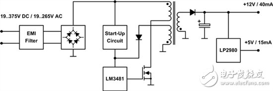
Figure 1: Block diagram of a flyback converter
The wide input voltage range is not only a challenge for the controller, but also a major challenge for the design of the transformer. For low power applications, the flyback converter is designed to operate in discontinuous conduction mode (DCCM) to achieve a small solution size because the inductance of the coupled inductor is also small. The peak current in this mode of operation is greater than the peak current in continuous conduction mode (CCM) - but they are still relatively small due to the small power. For larger power applications, flyback converters typically operate in CCM mode. At first glance DCCM seems to be the model for this flyback design with an output power of approximately 500mW.
To avoid large switching losses in the upper limit of the input voltage, the switching frequency should be relatively low. In this design, it is set to 130 kHz so that the fundamental is below the lower limit of 150 kHz for electromagnetic interference (EMI) measurements. If the converter is assumed to operate only in DCCM mode, then the duty cycle is in a range from 70% up to 4% (the turns ratio is 3.58:1, 750μH of primary inductance). To reduce component stress, you should increase the minimum duty cycle by keeping the turns ratio constant and changing the primary inductance to 4mH. Now, for low input voltages, the converter operates in CCM mode; for high input voltages, the converter operates in DCCM mode.
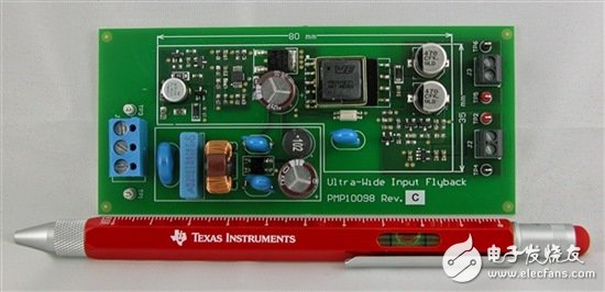
Figure 2: Low Power Flyback TI Designs Reference Design with Ultra Wide Input Voltage Range
| About Ei/Aiw Enameled Copper Wire |
Good resistance to abrasion and solvent.
Apply to B class motors, appliances, instrumentations, various types of electronic componentss and winding for coils.capable of working under extreme situations where strong resistibility against very hing and low temperature, powerful cryogen, hard radiation and forceful heat shock are needed.

Enamel Copper Wire,Ei/Aiw Enameled Copper Wire,Enameled Copper Wire Motor,Polyester Copper Wire
HENAN HUAYANG ELECTRICAL TECHNOLOGY GROUP CO.,LTD , https://www.huaonwire.com