The following is the circuit diagram of [bridge rectifier circuit, bridge rectifier circuit calculation and formula]
Bridge rectifier circuit
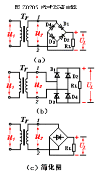
The bridge rectifier circuit is shown in Figure 5, where Figures (a), (b), and (c) are three different ways of drawing.

It consists of a power transformer, four rectifier diodes D1~4 and a load resistor RL. The four rectifier diodes are connected in the form of a bridge, so they are called bridge rectifiers.
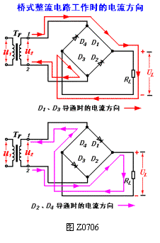
The working principle of the bridge rectifier circuit is shown in Figure 6. In the positive half cycle of u2, D1 and D3 are turned on, D2 and D4 are turned off, and the current is returned from the upper secondary end of the TR to the lower end of the TR via D1→RL→D3, and a half-wave rectified voltage is obtained on the load RL.

In the negative half cycle of u2, D1 and D3 are turned off, D2 and D4 are turned on, and the current is returned from the lower end of the Tr secondary to the upper end of the Tr via D2 → RL → D4, and the other half-wave rectified voltage is obtained on the load RL.
Thus, a voltage waveform identical to full-wave rectification is obtained on the load RL, and the current calculation is the same as the full-wave rectification, that is,
UL = 0.9U2 GS0709
IL = 0.9U2/RL GS0710
The average current flowing through each diode is
ID = IL/2 = 0.45 U2/RL
The highest reverse voltage that each diode is subjected to is

At present, the four rectifier diodes of the low-power bridge rectifier circuit are connected into a bridge and packaged into a rectifying device, called "silicon bridge" or "bridge stack". It is convenient to use, and the rectifier circuit is often simplified to the figure Z0705 (c )form.
The bridge rectifier circuit overcomes the shortcomings of the full-wave rectifier circuit that requires the center tap of the transformer secondary and the diode to withstand large back pressure, but uses two diodes. In today's fast development of semiconductor devices and low cost, this shortcoming is not prominent, and thus the bridge rectifier circuit is widely used in practice.
Fiber Optic Rotary Joint, also known as optical fiber slip ring, optical fiber rotary joint, optical hinge, etc., is used to solve the problem of optical signal transmission between opposite rotating components, that is, to ensure that the transmission of optical signals is not interrupted due to rotation.
fiber optic rotary joint,fiber optic slip ring,optical rotary joint
Dongguan Oubaibo Technology Co., Ltd. , https://www.sliproub.com
![<?echo $_SERVER['SERVER_NAME'];?>](/template/twentyseventeen/skin/images/header.jpg)