![<?echo $_SERVER['SERVER_NAME'];?>](/template/twentyseventeen/skin/images/header.jpg)
The structure of the open collector output is shown in Figure 1. The collector of the transistor on the right is not connected, so it is called open collector. (The left triode is used for inverting. When the input is "0", the output is also " 0â€). For Figure 1, when the input at the left end is "0", the front transistor is turned off (ie, the collector C and the emitter E are equivalent to being disconnected), so the 5V power supply is applied to the right transistor through the 1K resistor, and the right side is The transistor is turned on (that is, equivalent to a switch is closed); when the input at the left end is "1", the front transistor is turned on, and the rear transistor is turned off (equivalent to the switch is turned off).
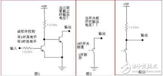
We simplify Figure 1 as shown in Figure 2. The switch in Figure 2 is controlled by software, with "1" open and "0" closed. It is obvious that when the switch is closed, the output is directly grounded, so the output level is zero. When the switch is turned off, the output is suspended, that is, high impedance. At this time, the level state is unknown. If the latter resistive load (even a very light load) is to ground, the level of the output is pulled low by this load, so this circuit cannot output a high level.
Look at Figure 3. The 1K resistor in Figure 3 is the pull-up resistor. If the switch is closed, there is current flowing from the 1K resistor and the switch, but since the switch-on and turn-off resistance is 0 (for our discussion, the switch resistance is not 0 in the actual case, and there is a saturation voltage drop for the triode), so The voltage on the switch is 0, that is, the output level is 0. If the switch is off, since the switch resistance is infinite (ibid., regardless of the actual leakage current), the current flowing through is 0, so the voltage drop across the 1K resistor is also 0, so the output voltage is 5V. This will output a high level. However, the internal resistance of this output is relatively large (ie 1KΩ). If a load with R is connected to the load, the final output voltage can be calculated as 5*R/(R+1000) volts, ie 5 /(1+1000/R) volts. Therefore, if you want to reach a certain voltage, R can not be too small. If R is really too small and the output voltage is not enough, then we can only increase the drive capability by reducing the 1K pull-up resistor. However, the pull-up resistor cannot be made too small, because when the switch is closed, a current will be generated. Since the current through which the switch can flow is limited, the value of the pull-up resistor is limited, and it is also necessary to consider when the output At low levels, the load may still be
A portion of the current will flow through the switch, so these current considerations should be combined to select the appropriate pull-up resistor.
2, open drain outputThe open drain is an open collector of the output transistor of the driving circuit, and the driving capability can be improved by an external pull-up resistor. This output uses a field effect transistor or metal oxide tube (MOS). The gate of the tube is connected to the output. The source is connected to the common terminal. The drain is floating (open) and there is no connection. Therefore, it needs to be connected during use. A resistor of appropriate resistance to the power supply can make this tube work normally. This resistor is called a pull-up resistor.
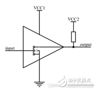
Open-drain output, in general, requires an external pull-up resistor to output a high level. For example, some chips are defined as open-drain outputs; some have open-drain outputs, etc. All external pull-up resistors are required for proper operation.
For open-drain (OD) outputs, the open-collector output is very similar. The transistor in the structure with the open collector output is replaced by a field effect transistor. Thus the collector becomes the drain and OC becomes the OD. The principle analysis is the same.
The biggest feature of the temperature regulating valve is that it only needs an ordinary 220V power supply and uses the energy of the regulated medium to directly automatically regulate and control the temperature of steam, hot water, hot oil and gas. It can also be used to prevent overheating or heat exchange. The valve has the advantages of simple structure, convenient operation, wide temperature regulation range, fast response time and reliable sealing performance, It can be adjusted at will during operation, so it is widely used in hot water supply in chemical industry, petroleum, food, light textile, hotels and restaurants.
Temperature Regulating Valve,New Needle Valve,Marine Butterfly Valve,Valve Pressure Gauge
Taizhou Jiabo Instrument Technology Co., Ltd. , https://www.jbcbyq.com