![<?echo $_SERVER['SERVER_NAME'];?>](/template/twentyseventeen/skin/images/header.jpg)
1. Introduction The servo motor is used as an actuator in an automatic control system that converts the received control signal into an angular displacement or angular velocity output of the shaft. There are three general control methods:
1 communication mode, using RS232 or RS485 way to communicate with the host computer to achieve control;
2 analog quantity control mode, using the size and polarity of the analog quantity to control the speed and direction of the motor;
3 differential signal control mode, using the frequency of the differential signal to control the motor speed.
Simple and convenient implementation of precise control of servo motor speed is a desirable goal in the field of industrial control. This paper mainly studies how to use the analog output of plc output to achieve more precise control of servo motor speed.
2. Control system circuit control device selects Siemens S7-200 series PLC CPU224XPCN, this type of PLC has input and output points. There is also an analog input point and an analog output point. This type of PLC has an analog module that can meet the needs of controlling the servo motor. The touch screen uses Siemens touch screen, model TP177B.
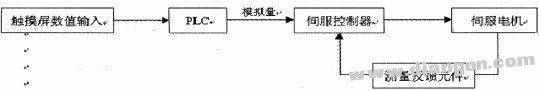
The specific control scheme is shown in Figure 1. The touch screen is the human-machine dialog interface. The initial command information should be input from here. The entered information is transferred to the PLC via the communication port. After the operation, the PLC outputs the analog quantity and is connected to the analog input port of the servo controller. The servo controller performs internal calculation on the received analog quantity, and then drives the servo motor to reach the corresponding speed. The servo motor feeds back the speed information to the servo controller through the speed measuring component to form a closed loop system, which achieves the effect of stable speed.
Figure 1 control scheme
The servo motor in the scheme has a design working speed range of 500 to 6000 RPM and an accuracy requirement of ±3 RPM.
3. Control process Set a dialog box on the touch screen, you can enter a 4-digit value, and then set the data property in this dialog box to the corresponding variable data in the PLC (such as VW310). The goal is that the motor can reach the same speed as the value when the value is entered in the dialog.
The analog output of the PLC output is 0 to 10V, and the corresponding shaping data is 0 to 32000; and the input analog quantity of the servo motor is 0 to 10V. The corresponding speed is 0-6500 RPM. Since these values ​​are theoretical, and finally hope that the input value corresponds to the upper speed. Therefore, the analog quantity is only used as an intermediate link for reference. The key considerations are input values, shaping data, and actual speed. After direct measurement, the test data is shown in Table 1.
It can be seen from Table 1 that the input value is far from the actual speed, and the only way is to convert the input value into an integer value that can correspond to the actual speed. But also first find the value corresponding to the highest speed and the lowest speed. Through experiments, the corresponding relationship is shown in Table 2.
Both the analog output of the PLC and the servo motor speed output are linear. The linear equations can be listed according to the data in Table 2, and the relationship between the input value and the shaped value can be calculated.
2711=500×a+b
30854=600×a+b
Solution: a=5117; b=152
Let the actual speed be x and the shaping value be y; then the relational equation is:
y=5117×x+152
Through the PLC. The realization requires the wife to use the digital operation instruction. Specifically, as shown in Figure 2, after the digital operation instruction realizes the corresponding relation operation, the data is directly transmitted to the analog output port to complete the conversion work (since the output port does not accept double word data) So only the word data, VB2232 can be). As shown in Figure 3, the analog output port of Figure 3 transmits instructions. Basically, the speed value is input from the dialog box, and the analog quantity is output after the PLC operation. The servo controller receives the analog drive servo motor, and the speed of the servo motor is equal to the input speed value. Through the actual test, the input value, the shaping value and the actual speed are measured as shown in Table 3.
4. Conclusion This paper proposes a method of controlling the servo motor using the analog output module equipped with the Siemens 200 series PLC. The method is simple, easy to implement, and can meet the working requirements of the rotational speed accuracy of ±3 RPM.
300W Medical Power Supply,300W Medical Device Power Supply,300W Medical Power Adapter,300W Rade Power Supplies
Shenzhen Longxc Power Supply Co., Ltd , https://www.longxcpower.com