![<?echo $_SERVER['SERVER_NAME'];?>](/template/twentyseventeen/skin/images/header.jpg)
Synchronous rectification is a new technology that uses a dedicated power MOSFET with very low on-resistance to replace the rectifier diode to reduce rectification losses. It can greatly improve the efficiency of the DC/DC converter and there is no dead zone voltage caused by the Schottky barrier voltage.
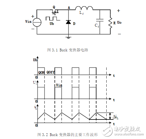
The Buck circuit is composed of a power transistor switch Q connected in series with the load, and its circuit is shown in Figure 3.1. The driving signal ub periodically controls the turning on and off of the power transistor Q. When the transistor is turned on, if the saturation voltage drop is ignored, the output voltage uo is equal to the input voltage; when the transistor is turned off, if the leakage current of the transistor is ignored, the output voltage is 0. The main working waveform of the circuit is shown in Figure 3.2.
The synchronous rectification buck circuit diagram is as follows:
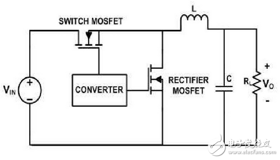
Synchronous rectification structure: replacing the rectifier diode with power mosfet can improve converter efficiency.
The average output voltage of the buck converter is always less than the input voltage.
When the current flowing through the inductor does not fall to zero during each cycle, the converter is defined to operate in continuous conduction mode.
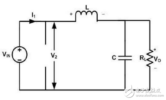
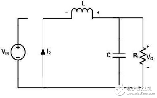
Equivalent circuit diagram when the converter switch is turned on
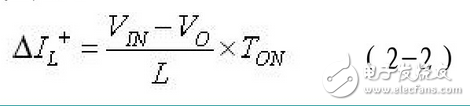
The potentials at the left and right ends of the inductor are Vin and Vo, respectively, and the relationship between the potentials is as follows:
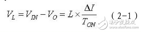
The inductor current rises linearly, at which point energy is stored in the inductor, as shown by the equation:
The equivalent circuit diagram when the converter switch is turned off is as follows:
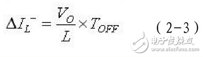
The voltage across the inductor is reversed and remains constant, and the inductor current decreases linearly, as shown by the equation:
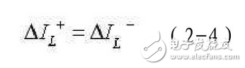
The increment and decrement of the inductor current must be equal during one switching cycle:
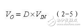
The relationship between the output voltage and the input voltage is as follows:
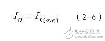
Throughout the switching cycle, the inductor delivers energy to the filter capacitor and load, while the filter capacitor has an average current of zero per cycle and a change in energy of zero. Therefore, the output load current is equal to the average value of the inductor current:
The waveform of the converter operating in continuous conduction mode is as follows:

Vapesoul Mod Vape is so convenient, portable, and small volume, you just need to take them
out of your pocket and take a puff, feel the cloud of smoke, and the fragrance of fruit surrounding you. It's so great.
We are the distributor of the Vapesoul & Voom vape brand, we sell vapesoul disposable vape,vapesoul vape bar, voom vape disposable, and so on.
We are also China's leading manufacturer and supplier of Disposable Vapes puff bars, disposable vape kit, e-cigarette
vape pens, and e-cigarette kit, and we specialize in disposable vapes, e-cigarette vape pens, e-cigarette kits, etc.
vapesoul mod vape kit, vapesoul mod vape pen,vapesoul mod vape box mod,vapesoul mod vape start kit, vapesoul mod e-cigarette kit
Ningbo Autrends International Trade Co.,Ltd. , https://www.mosvape.com