![<?echo $_SERVER['SERVER_NAME'];?>](/template/twentyseventeen/skin/images/header.jpg)
ZigBee is a low-power LAN protocol based on the IEEE802.15.4 standard. According to international standards, ZigBee technology is a short-range, low-power wireless communication technology. This name (also known as the Zigbee Protocol) comes from the bee's splay, because bees rely on flying and "zig" to shake the wings of the "dance" to convey the position of the pollen with the companion. That is to say, the bees rely on such a way to form a communication network in the group. It is characterized by close proximity, low complexity, self-organization, low power consumption, and low data rate. It is mainly suitable for use in the fields of automatic control and remote control and can be embedded in various devices.
In short, ZigBee is a cheap, low-power, short-range wireless networking communication technology. ZigBee is a wireless network protocol for low-speed short-distance transmission. The ZigBee protocol is a physical layer (PHY), a media access control layer (MAC), a transport layer (TL), a network layer (NWK), an application layer (APL), and the like from bottom to top. The physical layer and the media access control layer follow the IEEE 802.15.4 standard.
First, the board will be tested for burning1. Open the FlashGUI.exe software under the folder flashprogrammer. After the software is opened, the interface is as follows:
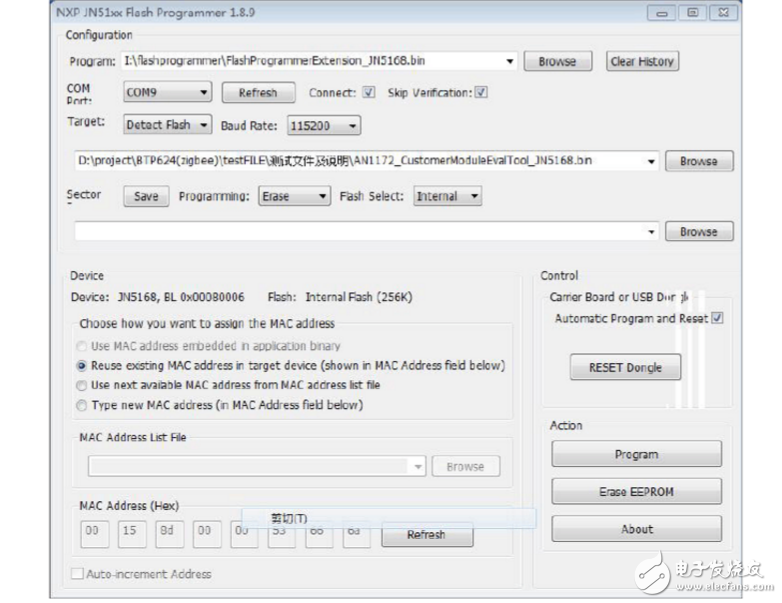
2. Click the Browse button on the FlashGUI.exe software interface to test the software.
AN1172_CustomerModuleEvalTool_JN5168.bin (Note: the test software is determined by the zigbee module chip, you need to confirm with the engineer which chip) Browse to the burning software
3. Click the com port: button on the FlashGUI.exe software interface, select the com port, and then click Program
Button, test software successfully burned into the board
Second, set the test mode of the board1. Insert the board into the computer, right click on the computer - Properties - Device Management - Port - View the temporary serial port of the board
slogan
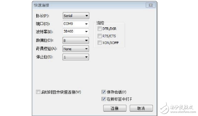
2. Open the SecureCRT software - click
Button---Set as shown in the figure below, port number selection
Select the port number you see in the computer in the first step, then click OK.
Note: The checkmark of this option must be removed, or the serial port cannot be printed.
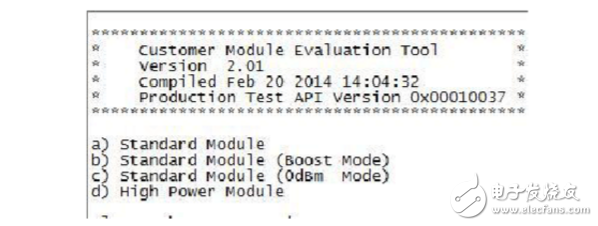
3. Click the connection button in the above figure, the serial port prints as shown below, and the board enters the test mode state.
1. Deep sleep mode current test: Deep sleep mode : Expected value is 100nA
Remarks: Since there is no nA-class power meter, it is currently not tested. The current ST products generally can't do nA level, only UA can be used, and can be tested with a multimeter.
2. Sleep mode without memory retenTIon current test: Sleep mode without memory
retenTIon : Expected value is 600nA.
Remarks: Since there is no nA-class power meter, it is currently not tested. The current ST products generally cannot be nA level, only UA can be used, and can be tested with a multimeter. 3. After POR current: After POR: 4.5mA
Test method: to be determined
4. Radio Transmit Current: Radio transmit : 18.1 mA
Test method: to be determined
5. Radio receive current: Radio receive : 19.6mA
Test method: to be determined
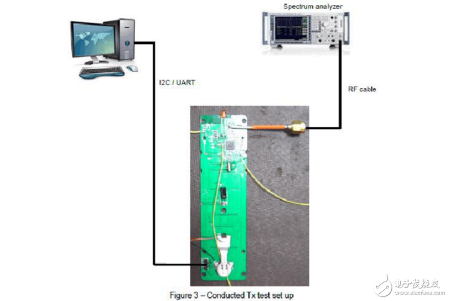
Fourth, TX Frequency Accuracy test1. Test the wiring diagram, open the SecureCRT software on your computer, and connect the computer and board with a USB cable.
2. In the serial port, set the board test mode as follows:
a) Standard Module---a) TX Power Test (CW)---- a) Output ConTInuous—Press +
Or - switch channels until channel18
3. Spectrum Analyzer Settings
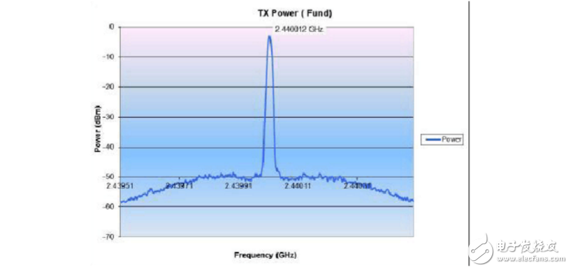
Set analyzer to : Center frequency = 2.44 GHz , span = 2 MHz , Ref amp = 0 dBm 4. Test screenshot
6. Test result plan and expected value
Measured frequency : 2.440 GHz
Ppm value = (2440012 - 2440000) / 2.440 = 4.9 ppm "25ppm (AddiTIonal +/-15ppm allowance for temp. & ageing)
7. (test value - the center frequency of this channel) / the center frequency of this channel = a value, this value is required to be less than
25PPm meets the requirements
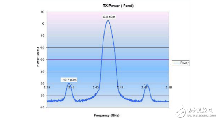
Five, TX Power test1. Test the wiring diagram Figure 3. In the serial port, set the board test mode as follows:
a) Standard Module--- b) TX Power Test (Modulated)--- a) Output Continuous
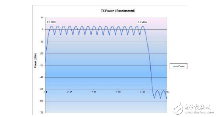
2. Spectrum analyzer settings:
Start freq = 2.4 GHz , Stop freq = 2.5 GHz , Ref amp = 10 dBm , sweep time = 100 ms , RBW = 3 MHz
Click TRACE to enter, click Trace to set Max Hold mode
3. In the serial port, first switch the channel to 11, then press + to switch to channel26 and read the test result.
Click the MKR button, then click the MKR→ button, click the peak point and the next peak point to read the power.
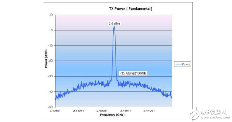
4. Test screenshot
5. Test criteria:
Required power greater than 2dBm
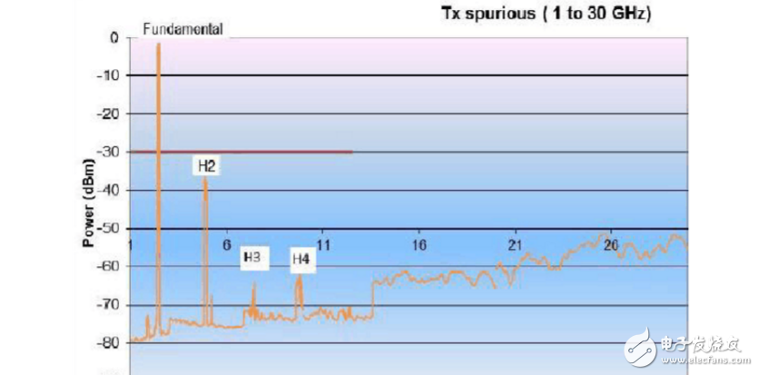
Six, TX spurious1. Test the wiring diagram Figure 3. In the serial port, set the board test mode as follows:
a) Standard Module---a) TX Power Test (CW)---- a) Output Continuous 2. Click the FREQ button, then click start, enter 1GHz, then click the stop button to enter 30GHz 3. The test results are shown below :
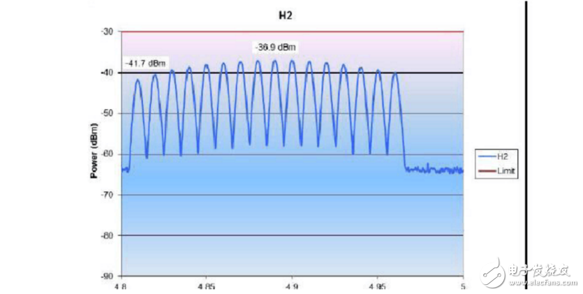
6. H2 point test:
Test wiring diagram Figure 3, in the serial port, the board test mode is set as follows:
a) Standard Module---a) TX Power Test (CW)---- a) Output Continuous
Click the FREQ button, then click start, enter 4.8GHz, then click the stop button to enter 5.0GHz, the test results are as follows:
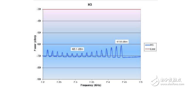
7. H3 point test:
Test wiring diagram Figure 3, in the serial port, the board test mode is set as follows:
a) Standard Module---a) TX Power Test (CW)---- a) Output Continuous
Click the FREQ button, then click start, enter 7.2GHz, then click the stop button to enter 7.5GHz, the test results are as follows:
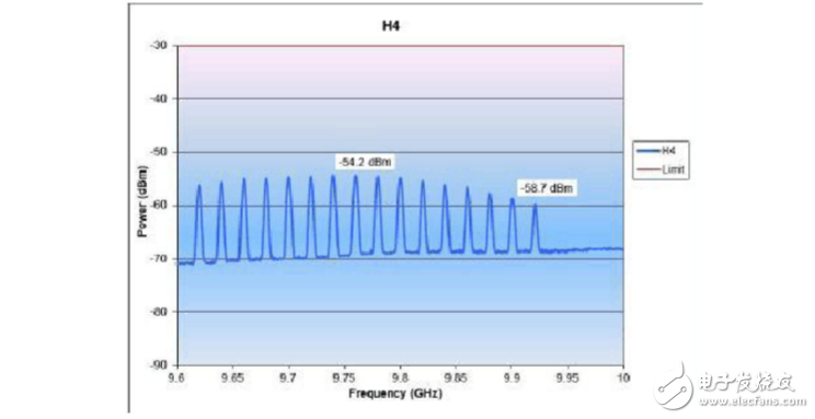
8. H4 point test:
Test wiring diagram Figure 3, in the serial port, set the board test mode as follows: a) Standard Module---a) TX Power Test (CW)---- a) Output Continuous Click the FREQ button, then click start, enter 9.6GHz , then click the stop button to enter 10GHz, the test results are as follows:
1. Test the wiring diagram Figure 3. In the serial port, set the board test mode as follows:
a) Standard Module---a) TX Power Test (CW)---- a) Output Continuous—Press + or - to switch channels until channel18
2. Spectrum Analyzer Settings
Center frequency = 2.44 GHz , span = 100 MHz, Ref amp = 0 dBm
Measure the spurs level at +/- 32 MHz frequency offset from the carrier frequency with the marker.
3. Test result screenshot
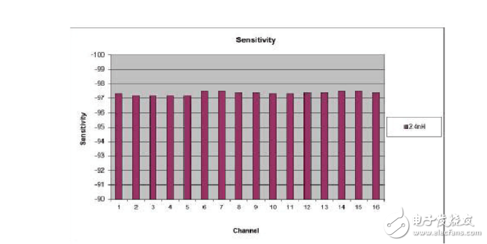
1. Test the wiring diagram Figure 3. In the serial port, set the board test mode as follows:
a) Standard Module---g) Trigger Packet Test---Press + or - to switch to channel11 channel 2. Test connection diagram
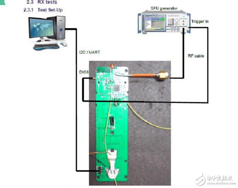
3. Set the SFU as follows:
The connection is automatically established and the PER (Packet Error Rate) is measured.
Decrease the level of the SFU at the RF input of the module until PER = 1%.
4. Test result screenshot:
Test method with TX spurious ten, Phase Noise
1. Test the wiring diagram Figure 3. In the serial port, set the board test mode as follows:
a) Standard Module---a) TX Power Test (CW)---- a) Output Continuous—Press + or - to switch channels until channel18 2. Spectrum Analyzer Settings:
Center frequency = 2.44 GHz , span = 1 MHz
(You can adjust the noise)
RBW (spectrum analyzer) = 10KHz (40dBc)
4. Test screenshot
Portable Diesel Generator(<400KW)
Portable Diesel Generator,Small Diesel Generator,Diesel Small Generator
Jinan Guohua Green Power Equipment Co.,Ltd. , https://www.guohuagenerator.com