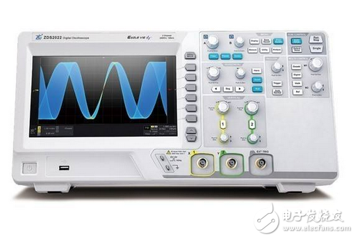
The digital oscilloscope is suitable for measuring fast pulse signals and is equipped with a high gain amplifier, so it has high sensitivity and can observe weak signals. In the debugging and testing of aviation, aerospace and electronics industry products, the application of digital oscilloscopes is becoming more and more popular. Now digital oscilloscopes are no longer limited to measuring the pulse parameters of a waveform. The spectrum can be tested by the time/frequency conversion of the FFT, and the signal jitter diagram can be obtained by the clock.

The digital oscilloscope is suitable for measuring fast pulse signals and is equipped with a high gain amplifier, so it has high sensitivity and can observe weak signals. In the debugging and testing of aviation, aerospace and electronics industry products, the application of digital oscilloscopes is becoming more and more popular. Now digital oscilloscopes are no longer limited to measuring the pulse parameters of a waveform. The spectrum can be tested by the time/frequency conversion of the FFT, and the signal jitter diagram can be obtained by the clock. It is therefore the preferred multi-purpose measuring instrument for testers.
1 Capture single pulse random signal
Some signals will only appear at system startup time and will disappear when the boot is complete. How do you capture such signals with a digital oscilloscope? Some testers use this method: observe on the oscilloscope display and press the stop button as soon as the signal is detected. Obviously, the success rate of this method is not high, especially for some high-speed signals. The correct way is to automatically capture a single pulse signal using the one-shot function of a digital oscilloscope. Take the TDS3054B digital oscilloscope produced by Tektronix as an example. Follow the steps below to set up the correct measurement.
(1) Adjust the vertical SCALE and horizontal SCALE to the appropriate signal range you want to see;
(2) Press the capture MENU button;
(3) Press the Resolution screen button;
(4) Select Normal capture resolution;
(5) Press the SINGLE SEQ button.
The SINGLE SEQ button sets the trigger parameters to the correct settings for a single pulse capture.
2 Optimize capture and read data
Before the next capture, we can adjust the vertical and horizontal controls to preview how the next capture might be displayed. When these controllers are adjusted, the current capture is reconfigured, expanded, or compressed. Such a preview is useful for optimizing settings before the next single pulse event is captured.
When another capture is made with the new vertical and horizontal settings, the captured signal details can be seen.
When reading data, if you find that the stored text has only the current screen data, and the resolution is time interval, you can use the screen extension function to display more test details. In addition, the new digital storage oscilloscopes use the completely open WINDOWS platform, supporting Matlab, LabVIEW, VB, VC and other software. Use these software to flexibly analyze and process data.
3 Measuring jitter in the periodic signal
Some high-end digital storage oscilloscopes have dedicated jitter measurement software for comprehensive jitter measurements. No jitter software can only compare signals over long periods of time with infinite persistence. In addition, we can use cursors to measure peak-to-peak jitter, which makes the measurements more realistic and reliable. Take Tektronix' TDS3054B digital oscilloscope as an example. Follow the steps below to set up the measurement.
(1) Press the CURSOR button;
(2) Press the Function screen button;
(3) Select the V Bars cursor;
(4) Press the Bring Both Cursors On Screen button to quickly position the cursor;
(5) Place a cursor on the first falling edge and another cursor on the last falling edge;
(6) Read the peak-to-peak jitter time.
4 Proper use of the probe to obtain a pure and real signal
Design and testers need to use an oscilloscope to get the most realistic signal when making any measurements. The application of the oscilloscope should not affect the signal itself in any way, but almost any test will have an effect on the signal characteristics. Proper use of the test probe is very important to minimize signal distortion. When connecting a probe to any input channel for the first time, the probe should be compensated to the oscilloscope input. This allows the oscilloscope's probe to be matched to the input channel for optimal measurement. When using the matching test probe, do not set the input impedance to 50Ω, because the impedance of the probe in parallel with the input impedance will make the input impedance of the test circuit lower than 50Ω. When measuring the electrical signal with high internal resistance, it will not be measured. The illusion of the signal.
In addition, since the ordinary probe usually has a grounding line, it will form a similar interference path with the looped antenna, which introduces a relatively large interference. To reduce interference, the method can be used to remove the probe cap without using the ground lead from the probe. Instead, use the probe tip and the location inside the probe to contact the measured point for measurement.
High Speed Blender,Ipl Laser Hair Removal,Diy Laser Hair Removal,Best Ipl Hair Removal,Epilator Ipl
SHENZHEN CHONDEKUAI TECHNOLOGY CO.LTD , https://www.szfourinone.com
![<?echo $_SERVER['SERVER_NAME'];?>](/template/twentyseventeen/skin/images/header.jpg)