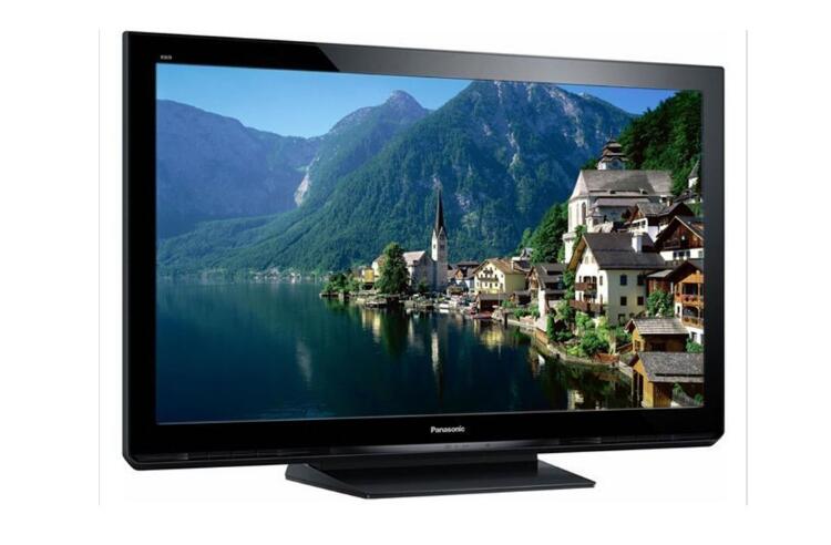
**Plasma TV Concept**
The full name of a Plasma TV is Plasma Display Panel, commonly referred to as Plasma TV in Chinese. It is a type of display technology that works by injecting a mixture of gases between two ultra-thin glass panels and applying voltage to cause the phosphor to emit light, thereby creating images. Compared to CRT (Cathode Ray Tube) displays, plasma TVs offer higher resolution, larger screen sizes, ultra-thin designs, and vibrant, bright colors. When compared to LCD (Liquid Crystal Display) technology, plasma TVs provide better brightness, higher contrast, wider viewing angles, and more vivid color reproduction.
Plasma display technology can be broadly categorized into two types based on their operation: Direct Current PDP (DC PDP), where the electrodes are directly in contact with the gas, and Alternating Current PDP (AC PDP), which features a dielectric layer covering the electrodes. There are also three main types of color PDPs developed: single-substrate (surface discharge) AC PDP, dual-substrate (opposite discharge) AC PDP, and pulse storage DC PDP.

**How Plasma TV Works**
A plasma display screen uses gas discharge to create images. Instead of traditional cathode ray tubes, it relies on plasma tubes as the light-emitting elements. These tubes are arranged together to form the entire screen, with each tube acting as a pixel. Each pixel consists of three sub-pixels—red, green, and blue—that combine to produce various shades and colors. This process is similar to how CRT displays work.
At the core of each plasma tube is the plasma itself—a state of matter composed of free-moving ions (charged atoms) and electrons (negatively charged particles). Normally, gas is made up of neutral atoms, with an equal number of protons and electrons. However, when a voltage is applied, some electrons gain energy and collide with gas atoms, causing them to become ionized and positively charged. As current flows through the plasma, these charged particles move toward each other, leading to collisions that excite the gas atoms and cause them to emit light. This process is similar to how fluorescent lamps operate.
Each small cell on the plasma screen contains neon and xenon gas. When struck by electrical discharges, these gases emit ultraviolet light, which is invisible to the human eye. However, this UV light excites the phosphor coating on the screen, causing it to glow and produce visible light.

**Plasma Screen Display Principle**
The lighting principle of a plasma screen is similar to that of a fluorescent lamp. It uses plasma tubes—each serving as a basic pixel—as the light-emitting elements. The screen is built on a glass substrate with small discharge cells spaced at regular intervals. When a voltage is applied, the neon-xenon gas inside these cells creates a plasma discharge, generating ultraviolet rays. These UV rays then stimulate the phosphor coating, which emits visible light and forms the image on the screen.
Various components support the functioning of a plasma TV:
- **Power Board**: Supplies power to the screen, motherboard, video processing board, and other modules.
- **X Drive Board**: Generates drive signals for the X electrodes based on timing signals from the logic board.
- **Y Drive Board**: Provides drive signals for the Y electrodes using timing signals from the logic board.
- **Logic Board**: Processes image signals from the main board and generates addressing signals for the X, Y drive boards, and address boards.
- **Logic BUFFER Board (E, F, G)**: Converts data and control signals from the logic board into signals compatible with COF.
- **YBUFFER Board (Upper and Lower)**: Transmits scanning signals from the Y drive board to the screen, divided into upper and lower sections.
- **COF (Chip on Film)**: Converts signals from the logic buffer board into address signals for the screen.
- **FPC (Flexible Printed Circuit)**: Connects the scan signal from the logic Y-BUFFER board to the Y scan electrode on the screen.
This complex system ensures that the plasma TV delivers high-quality visuals with accurate color representation and fast response times, making it a popular choice for large-screen entertainment systems.
There are many different versions of DIN Connectors. The name of each type comes from the number of pins the connector has (3-pin DIN, 4-pin DIN, etc.) Some of these pin numbers come in different configurations, with the pins arranged differently from one configuration to the next.
DIN cable connector 3-pin, 4-pin, 5-pin, 6-pin, 7-pin, 8-pin degree 180, 216, 240, 262, 270
DIN cables, DIN connector, telephone cable, computer cable, audio cable
ETOP WIREHARNESS LIMITED , https://www.etopwireharness.com
![<?echo $_SERVER['SERVER_NAME'];?>](/template/twentyseventeen/skin/images/header.jpg)