![<?echo $_SERVER['SERVER_NAME'];?>](/template/twentyseventeen/skin/images/header.jpg)
ã€Abstract】Based on the existing solution of vehicle monitoring terminal, the overall design scheme of vehicle monitoring terminal based on CDMA module is determined. The composition and function module of the system are introduced. The hardware design of the system and the corresponding functional unit software are given. design.
This article refers to the address: http://
With the development of wireless communication technology, Intelligent Transportation System (ITS) has been widely used. The ITS generally consists of four parts: the traffic information collection part, the vehicle dispatch control part, the electronic toll collection system and the traffic information service. Four of these parts require the participation of in-vehicle terminals, which are a very important part of the ITS system. Traditional in-vehicle monitoring terminal systems typically use a GSM/GPS solution. This solution is less costly and has been successfully applied in some areas. The most important function of the vehicle terminal is the collection of traffic information, providing accurate positioning of the vehicle and vehicle operation (including speed information, direction of travel, etc.). The positioning information and speed information are usually obtained by the external GPS module. However, when the vehicle enters the tunnel or parks next to the high-rise building, the vehicle is in the coverage area of ​​the GPS satellite. During this time, the dispatching center cannot accurately obtain the traffic of the vehicle. Information affects the reliability of the monitoring and dispatching system. This paper proposes an on-board monitoring terminal system with ATMEL 89S51 as the controller and CDMA module DTGS800 as the communication and positioning system platform.
1. Introduction to DTGS-800
The DTGS800 is a CDMA wireless communication module from AnyDATA.
The DTGS800 operates in the 832MHz band and consumes 0.32W of power. It has a data transfer rate of up to 153kbps, can be remotely controlled via AT commands, and has a built-in TCP/IP protocol stack for short message service. A chip with gpsOne capability is integrated inside the module to enable positioning using the gpsOne solution.
The main interfaces of the DTGS800 module include: Universal Asynchronous Serial Port UART, General Purpose I/O Port GPIO, Codec Interface CODEC, User Interface User Interface, and PM Interface.
2. System hardware design
The vehicle monitoring terminal is mainly used for real-time information interaction with the monitoring center, including:
Obtain location information and speed information of the vehicle; issue scheduling information; perform remote control in case of abnormality of the vehicle. In addition, the vehicle driver is provided with a mobile communication service, which can be used to make and receive calls, and even to make a three-way call. The hardware system is an embedded single-chip microcomputer system that comprehensively utilizes electronic technology and communication technology, and is mainly composed of a controller and a communication module.
The controller is the core of the vehicle monitoring terminal, which has a great impact on the safe operation and reliability of the entire system. In this design, the CPU selects ATMEL's 8-bit microcontroller 89C51RD2, which is a high-performance CMOS FLASH version of the CMOS single-chip 8-bit microcontroller 80C51. Features include: 1 64-Kbyte FLASH memory area for storing code and data; 256 bytes of internal RAM, 1 9-source 4-level interrupt controller and 3 timer/counters; 1 1792-byte XRAM , 1 hardware watchdog timer, SPI interface, keyboard, 1 more general serial channel for multi-processor communication (EUART) and acceleration mechanism (X2 Mode).
The CPU's fully static design reduces system power consumption and allows the clock frequency to drop to any value without data loss. There are also two software-selectable modes of operation that reduce the active state of the 8-bit clock divider, further reducing power consumption. In idle mode, the CPU is frozen and the peripherals and interrupt systems continue to operate. In power-down mode, RAM content is saved and all other functions are invalid.
The system's frame diagram is as follows:
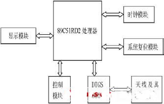
Figure 1 system structure framework
3. System software design
The system divides the software functions into modules in the form of tasks. The tasks implemented by the software include: task scheduling; acquisition of vehicle location information and speed information; acceptance, processing and transmission of short messages; dialing and receiving of calls; screen display.
The program flow is: after the vehicle is started, the system is powered on, firstly, the system is initialized, then the timer interrupt and the serial port interrupt are started. After the startup is completed, the system enters the interrupt monitoring state, and the data in the serial port buffer is scanned every 10 ms, and according to different states. Call different interface functions to implement various functions. The most important task of the vehicle monitoring terminal is the acquisition and transmission of real-time traffic information. The following focuses on the acquisition of GPS information and the reception and transmission of short messages.
3.1 serial port interrupt function
In this system, the processor controls the DTGS800 module by sending AT commands through the serial port. When an AT command is sent, the DTGS module exchanges data with the processor through the serial port. Therefore, how to carry out serial port data management is the key to the performance of the system. In the design of this paper, the interrupt-based management method is adopted, and a 200 Bytes serial port buffer is set to read the serial port receiving data in real time in the form of a circular queue. The steps to achieve are as follows:
3.1.1 Defining global variables
#define REC_BUF_LEN 200
Idata volatile BYTE datain; the length of the input data
Idata volatile BYTE dataout;; the length of the output data
BYTE xdata dat[REC_BUF_LEN]; serial buffer
3.1.2 Implementation of the operation function
Bit BuffOut(BYTE *dp); read data from the buffer
Bit BuffIn( BYTE *dp); write data to the buffer
3.1.3 Interrupt function
The processor communicates with the DTGS800 module through the serial port. When receiving short messages and there are incoming call reminders, the serial port interrupt will be triggered. Therefore, the core of the serial port interrupt function is to store the received data in the circular queue. The flow chart of its implementation is as follows:
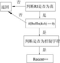
Figure 2 interrupt function flow chart
3.1.4 Interface Functions
In the actual working state, the call task and the short message task need to send data to the DTGS800 module through the serial port. The essence of these tasks is to send byte data to the serial port. So the most important thing about the interface function is to define the send byte function, defined as follows:
Void WriteToComm(BYTE c)
{
SBUF = c;
While (! TI);
TI = 0;
}
3.2 System Task Design
Different system states are defined according to different tasks, some of which are defined as follows:
Typedef enum
{
SYS_NET_FAIL, the network is unreachable
SYS_MISSED_CALL, missed call
SYS_CALL_SPEAKING, in a call
SYS_END_CALL, hanging up the phone
SYS_GET_GPS_INFO, get GPS data
SYS_SMS_INFO, short message reception
SYS_SMS_DISPLAY, short message display
}sys_app_sta;
After the system is started, enter the infinite loop in the main function and respond to different tasks for different states. Take the missed call as an example, define the following function:
If(cmp_com_str("MISSED_CALL", Locat, 1)) judgment status
{
Missed_call_deal(); missed call handler
Dataout = Locat;//go
Reccnt = Reccnt -4;
Clrline(line_1);
Display_app(0x82, "missed call:"); display function
Start_nom_ref();
Sys_state = SYS_IDLE_STATE; Enter idle state
Break;
}
3.2.1 Positioning task
The positioning task is responsible for collecting traffic information of the vehicle, including longitude, dimension, speed, direction of travel, etc., first querying the working state of the module before sending the positioning command, and then sending an AT command through the serial port to perform a positioning request, if the serial port receives the "OK" message , the system enters the SYS_GET_GPS_INFO state.
The received data is first stored in the buffer of the serial port, and the following GPS data processing functions are defined:
Typedef struct
{
BYTE UTC[10]; //Time
BYTE Latitude[10]; //latitude
BYTE Longitude[11]; //Longitude
BYTE rec_flg; //Status
BYTE Velocity[5]; //speed
BYTE Direction[5]; //direction
}GPS_STR;
Void Gps_Data(WORD head) Read data into the GPS data buffer
Void GpsData_PRO(void) parses the relevant information in the GPS for further processing;
After the GPS data analysis is completed, the traffic information of the vehicle is sent to the monitoring center by means of a short message.
3.2.2 Short message task
DTGS800 provides two different short message service protocols, one is simple protocol, suitable for some simple applications, and the other is extended protocol, the format of sending and receiving is more complicated. This system uses the extended SMS protocol.
3.2.2.1 Short message sending process
1) Send the command "AT+CAD?" to the module to detect the working status of the module. If the return value is 1, the module is working normally; if it is 0, the module is temporarily unavailable, wait for a few seconds for idle detection; 2) give The module sends the command "AT+SMSS?", and the status of the module is detected by the return value. If the module returns a value of 3, the module waits to accept the transmitted data; 3) sends the parsed GPS information, and sends the command "AT+ again" to the module. SMSS?", if the module returns a value of 1, it means that the message is sent successfully; 4) The display function is called, and "Send message sent successfully" is displayed on the screen.
3.2.2.2 Short message acceptance process
1) Judging the system status, such as receiving a short message, sending the command "AT+SMSR" to the module to read the received short message; 2) processing the received short message and storing it in the Buffer; calling the function UnicodeToGB( Convert the received Unicode code to GBK code; 3) Call the display function to cyclically display the unread short message. When the user reads the information, the system returns to the idle state and waits for the next instruction.
4 Conclusion
Through the actual measurement of the system, it is found that the vehicle monitoring terminal system can well realize the collection of vehicle traffic information, receive the scheduling information and control information in the monitoring, and has the characteristics of reliable communication and good scalability.
XLPE insulated flame retardant shipboard power cables 0.6/1kv 90℃
The shipboard power cables manufactured by Jiangsu Jiangyang Special Cable Co,.Ltd. has the following type: XLPE insulated flame retardant shipboard power cables, XLPE insulated flame retardant shipboard power cables(single sheath), XLPE insulated fire resistant shipboard power cables and XLPE insulated fire retardant shipboard power cables(single sheath.
The XLPE insulated flame retardant shipboard power cables 0.6/1kv 90℃ contains the next types: CJ86/SC, CJ96/SC, CJPJ/SC, CJPJ80/SC, CJPJ90/SC, CJPJ85/SC, CJPJ95/SC, CJ85/SC and CJ95/SC.

Flame Retardant Marine Power Cable
Xlpe Cable,Flame Retardant Marine Power Cable,Single Core Cables Sizes,Xlpe Swa Pvc Cable
Jiangsu Jiangyang Special Cable Co,.Ltd. , https://www.jymarinecable.com