![<?echo $_SERVER['SERVER_NAME'];?>](/template/twentyseventeen/skin/images/header.jpg)
The traditional DC brushless motor adopts a square wave control method, which is simple and easy to implement. At the same time, there are problems such as torque ripple and commutation noise. There are limitations in some application fields that require noise. For these applications, the use of sine wave control can solve this problem.
Brief introduction of sine wave control of DC brushless motor
The sine wave control of the brushless DC motor means that a certain voltage is applied to the motor winding to generate a sine current in the motor winding, and the purpose of controlling the motor torque is achieved by controlling the amplitude and phase of the sine current. Compared with the traditional square wave control, the phase current of the motor is sinusoidal and continuously changes without a sudden change in the commutation current, so the motor operates with low noise.
According to the complexity of the control, the sine wave control of the DC brushless motor can be divided into: simple sine wave control and complex sine wave control.
(1) Simple sine wave control:
Apply a certain voltage to the motor winding to make the motor phase voltage a sine wave. Since the motor winding is an inductive load, the motor phase current is also a sine wave. By controlling the amplitude and phase of the motor phase voltage to control the phase and amplitude of the current, the voltage loop control is relatively simple to implement.
(2) Complex sine wave control:
Different from simple sine wave control, the complex sine control target is the motor phase current, and the current loop is established. The purpose of controlling the motor is achieved by directly controlling the phase and amplitude of the phase current. Since the motor phase current is a sinusoidal signal, the current decoupling needs to be performed, which is more complicated. Commonly used are field-oriented control (FOC) and direct torque control (DTC).
This article will mainly introduce the principle and implementation of simple sine wave control.
Simple sine wave control principle
Simple sine wave control is to control the motor current by controlling the amplitude and phase of the sine phase voltage of the motor. Usually, a certain form of voltage is applied to the end of the motor to generate a sinusoidal phase voltage across the winding. Common generation methods are: sine PWM and space vector PWM. Because the principle of sine PWM is simple and easy to implement, it is usually used as the PWM generation method in simple sine wave control. Figure 1 is the BLDC control structure diagram, where Ux, Uy, Uz is the bridge arm voltage, Ua, Ub, Uc is the phase voltage of the motor winding, the following introduction of different types of PWM modulation will be based on this structure diagram.
Figure 1 DC brushless motor control block diagram
(1) Three-phase sinusoidal modulation PWM
Three-phase SPWM is the most common sinusoidal PWM generation method, that is, a sinusoidal voltage signal with a phase difference of 120 degrees is applied to the three terminal lines of the motor. Since the neutral point is 0, the motor phase voltage is also sinusoidal, and the phase and the applied sinusoidal voltage the same. as shown in picture 2.
Figure 2 Three-phase modulation SPWM terminal line voltage
(2) Minimum switching loss sinusoidal PWM
Unlike the common SPWM, when the switching loss minimum sinusoidal PWM is used, the voltages Ua, Ub, and Uc applied to the motor terminal line are not sinusoidal wave voltages. At this time, the motor center point voltage is not 0, but the motor phase voltage is still sinusoidal. Therefore, this type of control method is line voltage control. See Figure 3:
Figure 3 Switching loss minimum sinusoidal PWM terminal line voltage
Among them, Ux, Uy, Uz are the motor terminal line voltage, Ua, Ub, Uc are the motor phase voltage, and the phase difference of the phase voltage is 120 degrees. The relationship between Ux, Uy, Uz and Ua, Ub, Uc is as follows:


After the merger, Ux, Uy, Uz are as follows:
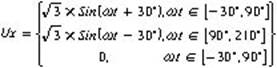

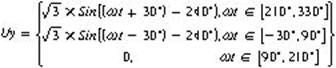
It can be seen that when using the minimum switching loss sinusoidal PWM, the Ux, Uy, Uz phase difference is 120 degrees, and it is in the form of a piecewise function, not a sinusoidal voltage, and the motor phase voltages Ua, Ub, Uc are still sinusoidal voltages. And the terminal voltage in the 120-degree zone is 0, that is, the corresponding switch is normally open or normally closed. Therefore, compared with the three-phase sinusoidal PWM, the switching loss is reduced by 1/3.
By controlling the phase and amplitude of Ux, Uy, Uz, Ux, Uy, Uz can be controlled to achieve the purpose of controlling the current.
Realization of simple sine wave control of DC brushless motor
system structure
The system structure is shown in Figure 4. The working principle is as follows: The Hall input signal is automatically filtered and sampled to obtain a reliable commutation signal. This information can be used to estimate the rotor angle and speed. The speed PI regulator calculates the magnitude of the ModulaTIon of the sinusoidal PWM based on the given speed value and the feedback speed value. The position estimation unit uses the rotation speed and the commutation information to estimate the rotor position angle Angle. The lead angle adjustment unit compensates for the lead angle Δ to obtain Angle. The SPWM unit uses ModulaTIon and Angle information to generate the minimum switching loss SPWM and outputs it to the inverter unit. The following content introduces the principle and implementation of each unit.
Figure 4 System block diagram
The generation of the minimum switching loss sinusoidal PWM
Since Ux, Uy and Uz are 120 degrees out of phase, Ux is used as an example for analysis.

Ux is a piecewise function,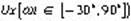 versus
 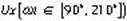 Is a sine function and takes
  symmetry. Only one of them needs to be realized, and the other is symmetrical.
The realization of:
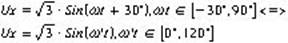
Therefore, it only needs to use a sine table of 0-120 degrees, that is, , Where M is the amplitude. The implementation of Uy and Uz is similar to Ux, with a phase difference of 120 °.
The amplitude and phase of the motor phase voltage can be controlled by controlling M and x.
Relationship between the minimum switching loss sinusoidal PWM control and the Hall position sensor
Generally, the brushless DC motor uses a Hall sensor to locate the rotor position. Since the traditional control method is square wave control, three Hall sensors can meet the requirements. The relationship between the position of the Hall sensor and the back EMF of the rotor is shown in Figure 5, that is, the Hall sensor is installed at a position where the back EMF is 30 °, 90 °, 150 °, 210 °, 270 °, and 330 °. The specific Hall output value is related to the specific installation method of the Hall.
Figure 5 The relationship between BLDC Hall sensor output and back EMF
The schematic diagram of the relationship between the terminal voltage of the motor and the output of the Hall sensor is shown in Figure 6 when the BLDC with minimum switching loss sinusoidal PWM is used to control the BLDC.
Figure 6 The relationship between the terminal line voltage and the state of the Hall when the switching loss minimum sinusoidal PWM is used
It can be seen from Fig. 2 that when the switching loss minimum sinusoidal PWM is used, the motor terminal line voltage leads the phase voltage by 30 °, so that the phase voltage of the motor is synchronized with the back EMF when the sine wave control is used.
Since the phase voltage leads the phase current, the phase current lags behind the back EMF.
Speed ​​calculation
The speed calculation depends on the Hall sensor. In an ideal state, the interval between two adjacent Hall states is 60 °. In actual applications, due to installation errors, the actual interval is not 60 °, which will introduce calculation errors. In this document, the output of a Hall sensor is used as a reference for speed calculation, as shown in Figure 7. The high and low levels are 180 degrees, which will not introduce installation errors. Use this information to calculate the motor speed.
Figure 7 The calculation formula of speed calculation is as follows: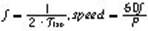 . Where: f is the electrical frequency, P is the number of motor pole pairs
Angle estimation
Unlike the square wave control, the angle in the sine wave control is continuously changing, and the three Hall sensors common in BLDC can only provide 6 angle information, namely 0 °, 60 °, 120 °, 180 °, 240 °, 300 °, other angle information cannot be obtained directly. The average speed method is usually used, assuming that the motor speed is stable within a certain period of time, and other angle information is obtained by interpolating the angle and speed information during the previous Hall commutation, as shown in Figure 8.
Figure 8 Angle estimation
 It can be seen that the motor speed fluctuation will directly affect the angle calculation error. In the scheme, the average value of the three adjacent 180 ° commutation times is used to calculate the speed information, as shown in Figure 9.
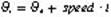
Figure 9 The speed calculated by the multiple average method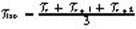 , In order to reduce the angle error caused by speed fluctuations.
Speed ​​PI
The speed control adopts PI regulator, the input is speed setting and speed feedback, and the output is ModulaTIon, which is the minimum sinusoidal PWM amplitude of switching loss. The formula is as follows:
among them: Is proportional gain,
  Is the integral gain, and y is the output of the PI mediator. In the specific implementation, the anti-integral saturation function is added to the integration link to limit the maximum and minimum values ​​of the integrator output, and at the same time, the saturation limit is added to the output value of the entire PI mediator. The implementation block diagram is as follows.
Figure 10 Block diagram of PI mediator
start up
Before the start of the brushless DC motor, the rotor is at a standstill, and only the Hall sensor can be used to obtain the absolute position information of the motor. Since there is no commutation, the motor speed information cannot be obtained, so the average speed method cannot be used to calculate the angle required for sine control information. Therefore, in the motor start-up phase, the sine control method cannot be directly cut, and the square wave control method is used for starting. After the motor is started and reliable commutation information is obtained, it can be switched into sine wave control. In order to prevent large speed fluctuations, it is necessary to pay attention to the smooth transition of the current phase and amplitude before and after switching.
The current waveform before and after ideal switching 11 is as follows.
Lead angle adjustment
It can be seen from the foregoing that the output of the Hall sensor reflects the back EMF information of the rotor, and the sine wave phase voltage generated according to the state of the Hall is in phase with the back EMF of the rotor. Since the motor is an inductive load, the phase current of the motor lags the phase voltage. That is, the motor phase current lags the back EMF. When the Hall's maximum torque is output, the motor phase current is synchronized with the back EMF, so the voltage phase needs to be adjusted so that the generated phase voltage leads the back EMF, that is, the lead angle Δ. Proper adjustment of Δ can make the phase current and the back EMF in the same phase, increase the output torque, and improve the system efficiency. The adjustment of the lead angle can be manually adjusted through an experimental form, or automatically adjusted using a certain algorithm.
Figure 11 Ideal switching from square wave control to sine wave control
Experimental results
The specific implementation of the control method proposed in this paper uses Infineon's high-performance 8-bit microcontroller XC866. XC866 integrates a dedicated motor control unit CCU6E (providing a dedicated BLDC control mode) and a high-performance ADC module, which is ideal for controlling DC brushless motors. The motor is a brushless DC fan with a rated power of 35W, and the number of pole pairs: 4. The square wave control is used at the start, and the sine wave control is cut when the speed is stable. Figure 12 shows the phase current of the motor running under the sinusoidal PWM control with minimum switching loss.
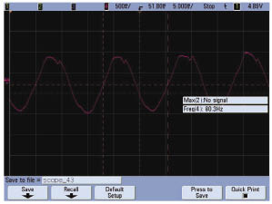
Fig. 12 BLDC phase current controlled by switching loss minimum sine wave
summary
This paper introduces a sine wave control scheme of DC brushless motor based on the minimum switching loss sinusoidal PWM, and implements and verifies the system based on Infineon high-performance 8-bit microcontroller XC866. Compared with the traditional square wave control, due to the use of sine wave drive technology, the motor running noise is low, and the switching loss is reduced by 1/3 compared with SPWM, which can well meet the requirements of noise and efficiency in DC brushless fan applications. Such control schemes will have great application prospects.
Brief introduction of sine wave control of DC brushless motor
The sine wave control of the brushless DC motor means that a certain voltage is applied to the motor winding to generate a sine current in the motor winding, and the purpose of controlling the motor torque is achieved by controlling the amplitude and phase of the sine current. Compared with the traditional square wave control, the phase current of the motor is sinusoidal and continuously changes without a sudden change in the commutation current, so the motor operates with low noise.
According to the complexity of the control, the sine wave control of the DC brushless motor can be divided into: simple sine wave control and complex sine wave control.
(1) Simple sine wave control:
Apply a certain voltage to the motor winding to make the motor phase voltage a sine wave. Since the motor winding is an inductive load, the motor phase current is also a sine wave. By controlling the amplitude and phase of the motor phase voltage to control the phase and amplitude of the current, the voltage loop control is relatively simple to implement.
(2) Complex sine wave control:
Different from simple sine wave control, the complex sine control target is the motor phase current, and the current loop is established. The purpose of controlling the motor is achieved by directly controlling the phase and amplitude of the phase current. Since the motor phase current is a sinusoidal signal, the current decoupling needs to be performed, which is more complicated. Commonly used are field-oriented control (FOC) and direct torque control (DTC).
This article will mainly introduce the principle and implementation of simple sine wave control.
Simple sine wave control principle
Simple sine wave control is to control the motor current by controlling the amplitude and phase of the sine phase voltage of the motor. Usually, a certain form of voltage is applied to the end of the motor to generate a sinusoidal phase voltage across the winding. Common generation methods are: sine PWM and space vector PWM. Because the principle of sine PWM is simple and easy to implement, it is usually used as the PWM generation method in simple sine wave control. Figure 1 is the BLDC control structure diagram, where Ux, Uy, Uz is the bridge arm voltage, Ua, Ub, Uc is the phase voltage of the motor winding, the following introduction of different types of PWM modulation will be based on this structure diagram.
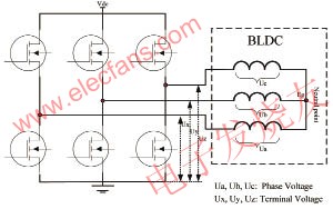
Figure 1 DC brushless motor control block diagram
(1) Three-phase sinusoidal modulation PWM
Three-phase SPWM is the most common sinusoidal PWM generation method, that is, a sinusoidal voltage signal with a phase difference of 120 degrees is applied to the three terminal lines of the motor. Since the neutral point is 0, the motor phase voltage is also sinusoidal, and the phase and the applied sinusoidal voltage the same. as shown in picture 2.
Figure 2 Three-phase modulation SPWM terminal line voltage
(2) Minimum switching loss sinusoidal PWM
Unlike the common SPWM, when the switching loss minimum sinusoidal PWM is used, the voltages Ua, Ub, and Uc applied to the motor terminal line are not sinusoidal wave voltages. At this time, the motor center point voltage is not 0, but the motor phase voltage is still sinusoidal. Therefore, this type of control method is line voltage control. See Figure 3:

Figure 3 Switching loss minimum sinusoidal PWM terminal line voltage
Among them, Ux, Uy, Uz are the motor terminal line voltage, Ua, Ub, Uc are the motor phase voltage, and the phase difference of the phase voltage is 120 degrees. The relationship between Ux, Uy, Uz and Ua, Ub, Uc is as follows:
After the merger, Ux, Uy, Uz are as follows:
It can be seen that when using the minimum switching loss sinusoidal PWM, the Ux, Uy, Uz phase difference is 120 degrees, and it is in the form of a piecewise function, not a sinusoidal voltage, and the motor phase voltages Ua, Ub, Uc are still sinusoidal voltages. And the terminal voltage in the 120-degree zone is 0, that is, the corresponding switch is normally open or normally closed. Therefore, compared with the three-phase sinusoidal PWM, the switching loss is reduced by 1/3.
By controlling the phase and amplitude of Ux, Uy, Uz, Ux, Uy, Uz can be controlled to achieve the purpose of controlling the current.
Realization of simple sine wave control of DC brushless motor
system structure
The system structure is shown in Figure 4. The working principle is as follows: The Hall input signal is automatically filtered and sampled to obtain a reliable commutation signal. This information can be used to estimate the rotor angle and speed. The speed PI regulator calculates the magnitude of the ModulaTIon of the sinusoidal PWM based on the given speed value and the feedback speed value. The position estimation unit uses the rotation speed and the commutation information to estimate the rotor position angle Angle. The lead angle adjustment unit compensates for the lead angle Δ to obtain Angle. The SPWM unit uses ModulaTIon and Angle information to generate the minimum switching loss SPWM and outputs it to the inverter unit. The following content introduces the principle and implementation of each unit.
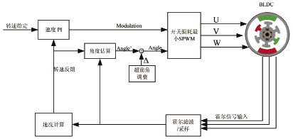
Figure 4 System block diagram
The generation of the minimum switching loss sinusoidal PWM
Since Ux, Uy and Uz are 120 degrees out of phase, Ux is used as an example for analysis.
Ux is a piecewise function,
Therefore, it only needs to use a sine table of 0-120 degrees, that is,
The amplitude and phase of the motor phase voltage can be controlled by controlling M and x.
Relationship between the minimum switching loss sinusoidal PWM control and the Hall position sensor
Generally, the brushless DC motor uses a Hall sensor to locate the rotor position. Since the traditional control method is square wave control, three Hall sensors can meet the requirements. The relationship between the position of the Hall sensor and the back EMF of the rotor is shown in Figure 5, that is, the Hall sensor is installed at a position where the back EMF is 30 °, 90 °, 150 °, 210 °, 270 °, and 330 °. The specific Hall output value is related to the specific installation method of the Hall.

Figure 5 The relationship between BLDC Hall sensor output and back EMF
The schematic diagram of the relationship between the terminal voltage of the motor and the output of the Hall sensor is shown in Figure 6 when the BLDC with minimum switching loss sinusoidal PWM is used to control the BLDC.
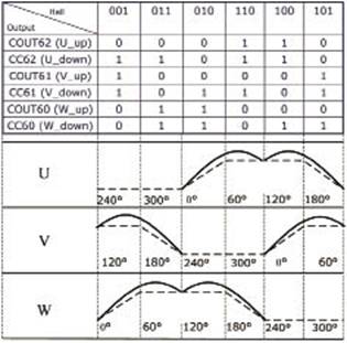
Figure 6 The relationship between the terminal line voltage and the state of the Hall when the switching loss minimum sinusoidal PWM is used
It can be seen from Fig. 2 that when the switching loss minimum sinusoidal PWM is used, the motor terminal line voltage leads the phase voltage by 30 °, so that the phase voltage of the motor is synchronized with the back EMF when the sine wave control is used.
Since the phase voltage leads the phase current, the phase current lags behind the back EMF.
Speed ​​calculation
The speed calculation depends on the Hall sensor. In an ideal state, the interval between two adjacent Hall states is 60 °. In actual applications, due to installation errors, the actual interval is not 60 °, which will introduce calculation errors. In this document, the output of a Hall sensor is used as a reference for speed calculation, as shown in Figure 7. The high and low levels are 180 degrees, which will not introduce installation errors. Use this information to calculate the motor speed.

Figure 7 The calculation formula of speed calculation is as follows:
Angle estimation
Unlike the square wave control, the angle in the sine wave control is continuously changing, and the three Hall sensors common in BLDC can only provide 6 angle information, namely 0 °, 60 °, 120 °, 180 °, 240 °, 300 °, other angle information cannot be obtained directly. The average speed method is usually used, assuming that the motor speed is stable within a certain period of time, and other angle information is obtained by interpolating the angle and speed information during the previous Hall commutation, as shown in Figure 8.
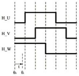
Figure 8 Angle estimation
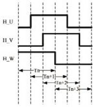
Figure 9 The speed calculated by the multiple average method
Speed ​​PI
The speed control adopts PI regulator, the input is speed setting and speed feedback, and the output is ModulaTIon, which is the minimum sinusoidal PWM amplitude of switching loss. The formula is as follows:
among them:
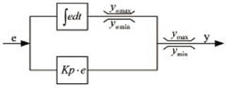
Figure 10 Block diagram of PI mediator
start up
Before the start of the brushless DC motor, the rotor is at a standstill, and only the Hall sensor can be used to obtain the absolute position information of the motor. Since there is no commutation, the motor speed information cannot be obtained, so the average speed method cannot be used to calculate the angle required for sine control information. Therefore, in the motor start-up phase, the sine control method cannot be directly cut, and the square wave control method is used for starting. After the motor is started and reliable commutation information is obtained, it can be switched into sine wave control. In order to prevent large speed fluctuations, it is necessary to pay attention to the smooth transition of the current phase and amplitude before and after switching.
The current waveform before and after ideal switching 11 is as follows.
Lead angle adjustment
It can be seen from the foregoing that the output of the Hall sensor reflects the back EMF information of the rotor, and the sine wave phase voltage generated according to the state of the Hall is in phase with the back EMF of the rotor. Since the motor is an inductive load, the phase current of the motor lags the phase voltage. That is, the motor phase current lags the back EMF. When the Hall's maximum torque is output, the motor phase current is synchronized with the back EMF, so the voltage phase needs to be adjusted so that the generated phase voltage leads the back EMF, that is, the lead angle Δ. Proper adjustment of Δ can make the phase current and the back EMF in the same phase, increase the output torque, and improve the system efficiency. The adjustment of the lead angle can be manually adjusted through an experimental form, or automatically adjusted using a certain algorithm.
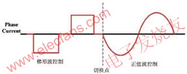
Figure 11 Ideal switching from square wave control to sine wave control
Experimental results
The specific implementation of the control method proposed in this paper uses Infineon's high-performance 8-bit microcontroller XC866. XC866 integrates a dedicated motor control unit CCU6E (providing a dedicated BLDC control mode) and a high-performance ADC module, which is ideal for controlling DC brushless motors. The motor is a brushless DC fan with a rated power of 35W, and the number of pole pairs: 4. The square wave control is used at the start, and the sine wave control is cut when the speed is stable. Figure 12 shows the phase current of the motor running under the sinusoidal PWM control with minimum switching loss.
Fig. 12 BLDC phase current controlled by switching loss minimum sine wave
summary
This paper introduces a sine wave control scheme of DC brushless motor based on the minimum switching loss sinusoidal PWM, and implements and verifies the system based on Infineon high-performance 8-bit microcontroller XC866. Compared with the traditional square wave control, due to the use of sine wave drive technology, the motor running noise is low, and the switching loss is reduced by 1/3 compared with SPWM, which can well meet the requirements of noise and efficiency in DC brushless fan applications. Such control schemes will have great application prospects.
Swivel Disk socket circular design, compact and simple. Power Strip Round 360 ° distribution socket, large spacing, multiple plugs at the same time.
Double break switch + Overload Protection.
Fireproof ABS Plastic, PVC copper cable, Use standard plug. Easy and safe to use for elderly and children.
Qualified Power Cord allowing you extend the outlet 6ft (2 meters) away from the wall or even further.
Extension Cord Round,Swivel Disc Socket,Power Strip Round,Electric Plug Portable Socket
ZhongShan JITONGLONG Plastic Hardware Co. Ltd. , https://www.toukoo-electronics.com