![<?echo $_SERVER['SERVER_NAME'];?>](/template/twentyseventeen/skin/images/header.jpg)
Abstract: This article introduces a signal detection method-frequency matching. The principle of the frequency matching algorithm is described in detail. Matlab is used to prove the correctness of the algorithm theoretically. On this basis, a synthesizable RTL Verilog model is used. The algorithm is described. The simulation of the integrated netlist verifies the feasibility of the hardware implementation of the frequency matching algorithm. Finally, according to the principle of frequency matching, a high-precision digital frequency detector is implemented, and the relevant accuracy values ​​are given.
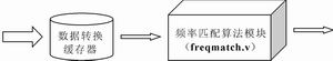
Figure 1 Block diagram of the frequency matching algorithm
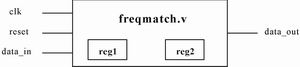
Figure 2 The internal structure of the frequency matching algorithm module
Foreword For unknown signals, Fourier transform can be used to detect the spectrum distribution in the signal. However, the results of the Fourier transform can only see which frequencies are included in the signal, and the distribution of the amplitude of a certain frequency in the time domain is unknown. In order to understand the distribution of the amplitude of a certain frequency in the time domain, you can Determined by frequency matching. Similarly, if you know that a certain signal contains a certain frequency, you can also detect the time domain where the amplitude of that frequency in the signal is located by frequency matching.
The so-called frequency matching is to use a frequency signal (hereinafter referred to as a matching signal) to perform correlation operations with an unknown signal (hereinafter referred to as a matched signal). Because the correlation operation can be used to detect the similarity of the two signals, the purpose of the correlation operation is to amplify the part of the matched signal that is the same as or close to the frequency of the matched signal, so that you can figure out the frequency of the matched signal The distribution of the frequency in the matched signal. The matching signal must be a single frequency signal, so the most ideal matching signal is of course a trigonometric function. This article uses trigonometric functions as an example to describe the principles and methods of frequency matching.
Implementation method of frequency matching The signal in practical application is usually discrete. Therefore, this article only discusses the discrete signal. Frequency matching can be used to detect, identify, and extract discrete signals. The following describes the realization method of discrete signal frequency matching.
Suppose the matched discrete signal is X (m), and its sampling frequency is fs, and the matched discrete signal is the sum. The frequency matching operation of the discrete signal is as follows:
(1)
(2)
(3)
Where N depends on the actual situation, usually an integer multiple.
The discrete function M (n) obtained by matching operation has the following properties: if the frequency of X (n) in the interval [n1, n2] is w, then M (n) will have a peak value in the interval [n1, n2] , That is, the value of M (n) in the interval [n1, n2] will be significantly larger than the value elsewhere.
DSP Implementation of Frequency Matching The following briefly introduces the DSP implementation method of frequency matching. The main part of the frequency matching algorithm is to calculate M1 (n) and M2 (n). Frequency matching DSP implementation methods can be divided into two types: single sampling and block sampling. In the single sampling mode, only one sample value arrives in each sampling period, and only one signal output value is generated in each sampling period. Therefore, the frequency matching achieved by single sampling must be performed in real time. In the block sampling mode, multiple sample values ​​arrive in each block period, and multiple signal output values ​​can be generated in each block period. Block sampling can process all input sample values ​​quickly or slowly according to actual needs.
Here will use block sampling mode to achieve frequency matching, in order to save memory and software overhead, most DSP hardware can implement circular memory, here frequency matching DSP also uses a circular buffer to achieve. For the input new sample value, the new sample value is entered and the old sample value overflows, which can save software overhead. The DSP implementation of frequency matching requires 3 circular buffers to store X (n), sin (n) and cos (n) respectively. Among them, X (n) needs to receive multiple sample values ​​in each block period. When the new sample value enters the circular buffer, the old sample value overflows. Since sin (n) and cos (n) are periodic functions, there is no need to input the sample value to its circular buffer every block cycle, just store the sample value of one cycle to the buffer in the first block cycle In the device. During the processing, in each block cycle, there is no need to load the values ​​of sin (n) and cos (n) into the circular buffer, just update the index pointer of the circular buffer, and for X (n) Circular buffer. Each block period must input a new sample value, and the index of the circular buffer indexer needs to be updated.
In order to understand the above implementation ideas, a simple example: set the sampled block length to 4, the number of points for correlation operations to 5, the length of the circular buffer holding the X (n) value to 8; set the period of the triangular discrete function to 5 (In practical applications, usually the number of points for correlation operations = the period of the triangular discrete function), considering that the length of the circular buffer must be a power of 2, so save the circular buffers of sin (n) and cos (n) The length is also 8. In the first block cycle, the first output set {M1 (0), M1 (1), M1 (2), M1 (3)} is calculated as follows: (4)
It can be seen from equation (4) that in the first block cycle, 8 sample values ​​X (0) ~ X (7) need to be obtained from the buffer. Similarly, it can be derived that in the second block cycle, X (4) ~ X (11) needs to be obtained from the buffer, and in the third block cycle, X (8) ~ X (15) needs to be obtained from the buffer. Therefore, after the second block cycle, 4 new samples should be loaded into the circular buffer in sequence. At the beginning of a block cycle, the index pointer of the circular buffer always points to the first sample value used in the block cycle, so the index pointer of the circular buffer of X (n) should be calculated according to equation (5) .
Indexer pointer = [previous pointer + block length] mod buffer length (5)
Since sin (n) is a function with a period of 5, it is only necessary to load 5 samples into the circular buffer of sin (n) in the first block period. The index of the circular buffer index of sin (n) should be calculated according to equation (6).
Indexer pointer = [previous pointer + block length] period of mod triangular discrete function (6)
When calculating M2 (n), the implementation method of X (n) circular buffer is as described above. The implementation method of cos (n) circular buffer is the same as that of sin (n), and its circular buffer index pointer The calculation also follows equation (6).
Using Verilog HDL to implement the frequency matching algorithm The frequency matching algorithm is not very complicated, so you can use Verilog HDL to implement the algorithm, and then download the generated netlist file to the FPGA. The structural block diagram of the frequency matching algorithm using Verilog HDL is shown in Figure 1.
Figure 1 contains two modules, in which the function of the data conversion buffer is to realize data format conversion and data caching. Data format conversion is to convert the format of data received from the outside into a data format that can be processed by the frequency matching algorithm module. Data caching It is to store the received large amount of data in the register, and then send a piece of data to the frequency matching algorithm module every clock cycle. The frequency matching algorithm module is the core of the entire system. When this module is implemented, a two-stage pipeline is used, which greatly speeds up the data processing speed. The internal structure of the frequency matching algorithm module is shown in Figure 2, where reg1 and reg2 are used to save the values ​​of sin (n) and cos (n).
The code described by the synthesizable RTL Verilog model of the frequency matching algorithm module is saved in the freqmatch.v file. In addition, during the design process, the top-level test module file t_freqmatch.v was also written. In this file, the simulation data generated by Matlab (stored in data.txt) was first read into the buffer, and then Send a data to the freqmatch module within the clock cycle. The data in the data.txt file contains three parts. The first part is random noise, the middle is a sinusoidal signal with a frequency of 500 Hz, and the latter part is a sinusoidal signal with a frequency of 1000 Hz. In the freqmatch.v file, set the frequency of the matching signal to 500 Hz. Through simulation, the freqmatch module can effectively extract the sinusoidal signal with a frequency of 500 Hz in the middle part.
Conclusion In the design process, the author wrote a synthesizable RTL Verilog module for the digital frequency detector, and through simulation and synthesis, its scale can be controlled within a reasonable range. In addition, the accuracy of the frequency detector can be improved by increasing the number of correlation operations in frequency matching. And an improved frequency matching algorithm is used in the design, so that the hardware scale will not increase with the increase of the number of points for related operations. Because the frequency matching detector is very similar to the frequency filter, the frequency filter parameters are used here to describe the frequency detector. Tables 1 and 2 give the parameters of several frequency detectors that have been implemented according to the frequency matching principle ( The pass band in the table refers to the frequency band that can be detected when the matching frequency is detected).
Finally, it should be pointed out that the frequency detector discussed in this article is very similar to the frequency filter, but they are different. When using an ideal frequency detector to process a signal, a certain frequency signal can be extracted, but the difference in the amplitude of the frequency signal in the original signal is erased, that is, the amplitude of the frequency signal is a constant value in the output signal. When an ideal filter is used to process a signal, not only can a certain frequency signal be extracted, but other characteristics of the frequency signal will not be changed.
Solar Security Light,Solar Led Flood Lights,Outdoor Solar Security Lights,300W Solar Flood Lights
Jiangmen Biaosheng Solar Energy Technology Co., Ltd. , https://www.bsprosolar.com