![<?echo $_SERVER['SERVER_NAME'];?>](/template/twentyseventeen/skin/images/header.jpg)
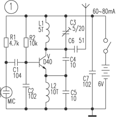
Mono channel FM transmitter circuit Figure 1 is a more classic 1.5km single tube FM transmitter circuit. The key component in the circuit is the transmitting transistor, mostly using D40, D50, 2N3866, etc., the working current is 60 ~ 80mA. However, the above transistors are difficult to purchase, and the prices are higher and there are more fakes. The author chooses other transistor experiments. The relatively easy-to-purchase transistors C2053 and C1970 are quite good. The actual line-of-sight communication distance is greater than 1.5 km. The author has also replaced the D40 tube with an ordinary triode 8050, with an operating current of 60 to 80 mA, but the launch distance is less than 1.5 km. If it is changed to 9018, the operating current is smaller and the launch distance is shorter. In addition to the transmitting transistor in the circuit, the parameter selection of the coil L1 and the capacitor C3 is more important. If the selection is improper, it will not vibrate or the operating frequency will exceed the range of 88 ~ 108MHz. Among them, L1 and L2 can use ∮0.31mm enameled wire on ∮3.5mm round bar to wind 5 turns and 10 turns in a single layer, C3 selects 5 ~ 20pF ceramic or polyester adjustable capacitor. In actual production, the capacitor C5 can be omitted, and L2 can also be replaced by a common inductance coil of 10 to 100 mH. If the launch distance is only a few tens of meters, then the battery voltage can be selected from 1.5 to 3V, and the D40 tube can be replaced with an inexpensive 9018, etc., which will consume less electricity. You can also refer to the "Electronic News" No. 8 of 2000 The fifth edition of "Simple Long-range Wireless FM Microphone" was slightly modified after the article.
The single-tube transmitter introduced in Figure 1 has the characteristics of simple circuit, large output power, and easy production, but it is inconvenient to connect high-frequency cables to send RF signals to the outdoor transmitting antenna, generally a whip antenna with a length of 0.7 to 0.9 m Directly connected to C5 for transmission, due to the Doppler effect, when people move near the antenna, the frequency drift phenomenon is very serious, so that the sound of the receiver with normal reception is distorted or silent. If you use this transmitter as a wireless microphone, you can imagine how serious the frequency drift is when you pinch the antenna.
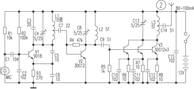
Figure 2 shows the 2km FM transmitter circuit. This circuit is divided into three stages: oscillation, frequency doubling, and power amplification. V1, C2 ~ C6, R2, R3 and L1 in the circuit form a capacitive three-point oscillator. Its oscillation frequency is mainly determined by the parameters of C3, C4 and L1, and its oscillation frequency is 44 ~ 54MHz. The signal is output from the center tap of L1 Then, C7 is coupled to V2 to amplify, and C8 and L2 select the 44-54MHz double frequency signal, that is, 88-108MHz. This signal is coupled from C9 to V3 for power amplification. V3 consists of three 3DG12 triodes connected in parallel. Expand the output power. When the circuit works normally, the current is about 80 ~ 100mA. The three 3DG12s that make up V3 can be added with appropriate heat sinks to prevent overheating. During production, L1 ~ L3 were wound with a single layer of ∮0.31mm enameled wire on a ∮3.5mm round bar.
Figure 3 shows a practical 50m FM wireless headset transmitter part circuit. The circuit is divided into oscillation and signal amplification. L1, C2 ~ C5, V1 and other components are similar to the improved capacitor three-point oscillator of the black-and-white TV high-frequency head local oscillator circuit. It has good frequency stability and does not run for a long time. Practice has proved that this improvement is adopted under amateur conditions. Type capacitor three-point oscillator is fully competent. The author directly soldered the collector of V1 with an electric soldering iron for a few seconds. Under the condition that the temperature of the triode is very high, the normal radio reception is still normal, and there is no frequency running phenomenon. The frequency of the oscillator is mainly determined by L1 and C2. By fine-tuning L1, the range of 88 to 108 MHz can be covered. The audio signal is coupled to the base of V1 via R6 and C11, and the capacitance between the e and b poles of V1 causes the oscillation frequency to change as the audio voltage changes to achieve frequency modulation. In this circuit, L1 ~ L3 are wound with a single layer of ∮0.31mm enameled wire on a ∮3.5mm round bar. By adjusting the inter-turn spacing of L1 to fine-tune the oscillation frequency, and then fine-tuning the inter-turn spacing of L2 and L3 to resonate with the oscillation frequency, the maximum output power is obtained.
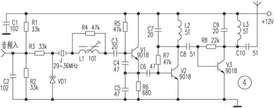
Figure 4 shows the crystal transmitter circuit. In the circuit, J, VD1, L1, C3 ~ C5, V1 form the crystal oscillation circuit. Because quartz crystal J has good frequency stability and is less affected by temperature, it is widely used in cordless phones and AV modulators. V1 is a 29 ~ 36MHz crystal oscillating transistor. The output of the emitter contains rich harmonic components. After being amplified by V2, the collector is composed of C7 and L2 and resonates at a network of 88 ~ 108MHz. A frequency-multiplied signal is selected (ie, 87 ~ 108MHz). Signal is the strongest), and then amplified by V3, L3, C9 frequency selection to obtain a more ideal frequency band signal. The process of frequency modulation is such that the change of the audio voltage causes the change of the capacitance between the VD1 poles. Due to the series connection of VD1 and crystal J, the oscillation frequency of the crystal also changes slightly. After three times the frequency, the frequency deviation is 29 ~ 36MHz. 3 times the frequency deviation. In practical applications, in order to obtain a suitable degree of modulation, a quartz crystal or ceramic vibrator with a large modulation frequency deviation can be selected, or a 6 to 12 frequency doubling circuit with a slightly complicated circuit can be used. If the input audio signal is weak, a primary voltage amplifier circuit can be added.


Follow WeChat
Interesting and informative information and technical dry goods

Download Audiophile APP
Create your own personal electronic circle

Follow the audiophile class
Lock the latest course activities and technical live broadcast
comment
Publish
related suggestion
[Photo] amateur radio 2m wave 4 unit box wireless ![[Photo] amateur radio 2m wave 4 unit box wireless](http://i.bosscdn.com/blog/20/06/41/5211134522.gif)
Posted at 2006-04-15 21:11 • 251 views
[Photo] The main points of amateur making parabolic antenna ![[Photo] The main points of amateur making parabolic antenna](http://i.bosscdn.com/blog/20/06/41/521115696.gif)
The main points of making parabolic antennas in amateurs --- F / D of parabolic antennas and radiation direction of feed
Posted at 2006-04-15 21:11 • 704 views
[Photo] Collection of amateur FM transmitting circuits (Part 2) ![[Photo] Collection of amateur FM transmitting circuits (Part 2)](http://i.bosscdn.com/blog/20/06/41/5205216934.jpg)
& n ...
Published on 2006-04-15 20:52 • 354 times read
[Photo] Collection of amateur FM transmitting circuits ![[Photo] Collection of amateur FM transmitting circuits]()
Source: Newsletter
Published on 2006-04-15 20:50 • 392 times read
Quit '; * / var login_content =' write an article ![]() '+ data.username +'
'+ data.username +'
Set exit '; $ (' # login_area '). Html (login_content); var win_width = $ (window) .width (); if (win_width> 1000) {$ ("# mine"). MouseDelay (200) .hover (function () {$ ("# mymenu"). show ();}, function () {$ ("# mymenu"). hide ();});}} else {var content = 'Login Registration'; $ ('# login_area'). html (content); $ (". special-login"). click (function (e) {$ .tActivityLogin (); return false;});}});} $ (function () {// comment ------------------------------- var comment = $ ("# comment"); var comment_input = $ ("# comContent"); // Submit comment click event interaction $ ("# comSubmit2"). on ('click', function () {var content = comment_input.text (); // Empty input box comment_input. html (""). focus (); // Submit data to server $ .ajax ({url: '/plus/arcComment.php', data: {aid: $ ("# webID"). val (), dopost : 'apiPubComment', content: content}, type: 'post', dataType: 'json', success: function (data) {// Data format returned: if (data.status == "successed") {// Build temporary comment DOM var dom = ''; dom + = '
'; dom + =' ![]() '; dom + ='
'; dom + ='
'; dom + ='
'+ data.data.username +' '; dom + ='
'; dom + =' '+ content +' '; dom + =' '; dom + =' just now '; dom + =' '; dom + =' '; // insert a temporary comment to the list $ ("# comment ") .append (dom);} if (data.status ==" failed ") {// alert (data.msg); layer.msg (data.msg);}}}); return false;}); (function () {/ * * Insert single sign-on JS * / var setHost = 'https://passport.elecfans.com'; // Set domain name var script = document.createElement ('script'); script.type = 'text / javascript'; script.src = setHost + '/public/pc/js/t.passport.js'; script.setAttribute ("id", "sso_script"); script.setAttribute ("data-ssoSite", setHost); script.setAttribute ("data-ssoReferer", encodeURIComponent (location.href)); script.setAttribute ("data-ssoSiteid", "11"); var body = document.getElementsByTagName ("body"). item ( 0); body.appendChild (script);}) () / * * It is recommended to modify the style of the article without a picture * * / $ (". Article .thumb"). Each (function () {if ($ (this). find ('img'). attr ('src') == "") {$ (this) .find ('img'). remove (); $ (this) .parent (). css ('padding-left ',' 0px ');}}); / * Baidu share * / window._bd_share_config = {common: {bdText: '', // Custom share content bdDesc: '', // Custom share summary bdUrl: window.location.href, // Custom share URL address bdPic: ''} , share: [{"bdSize": 60, "bdCustomStyle": true}]} with (document) 0 [(getElementsByTagName ('head') [0] || body) .appendChild (createElement ('script')). src = 'http://bdimg.share.baidu.com/static/api/js/share.js?cdnversion=' + ~ (-new Date () / 36e5)]; var add_url = '/ d / article / write / '; // var check_allow = "{: U (' Api / iscantalk ')}"; var check_allow = "/ d / api / iscantalk"; var click_items_length = $ ('. art_click_count '). length; if ( click_items_length> 0) {var id_str = ''; $ ('. art_click_count'). each (function () {id_str + = $ (this) .attr ('data-id') + ',';}) // var url = "{: U ('Api / getclickbyids')}"; var url = "/ d / api / getclickbyids"; var id_data = 'id_str =' + id_str; $ .ajax ({url: url, data: id_data, type: 'post', dataType: 'json', success: function (re) {if (re.list.length> = 1) {var list = re.list; for (var i in list) {var t emp_id = list [i] ['id']; var temp_span = $ (". art_click_count [data-id =" + temp_id + "]") temp_span.html (list [i] ['click']);}} }})} $ ("# comContent"). click (function () {if (now_uid == '') {$ .tActivityLogin (); return false;}}) $ (function () {var follow_wrap = $ ( ".author-collect"); var now_uid = "{$ _super ['uid']}"; var face_src = "{$ _super ['uface']}"; var getFollowNum = $ (". followNum strong"). html (); // Follow $ (window) .on ('click', '.author-collect', function () {if (now_uid == '') {$ .tActivityLogin (); return false;} if ( $ (this) .attr ('id') == 'follow') {$ .post ('/ d / user / follow', {tuid: article_user_id}, function (data) {// Data format returned: if (data.status == "successed") {$ (". followNum strong"). html (++ getFollowNum); follow_wrap.html ('followed'). attr ('id', 'cancelFollow'). css ( 'background', '# 999'); var follow_user = ' ![]() '; $ (' # follow_list '). append (follow_user);} if (data.status == "failed") {alert (data.msg);}});} else {// Unfollow if ($ ( this) .attr ('id') == 'cancelFollow') {$ .post ('/ d / user / cancelFollow', {tuid: article_user_id}, function (data) {// Data format returned: if (data .status == "successed") {follow_wrap.html ('Follow'). attr ('id', 'follow'). css ('background', '# f90'); $ (". followNum strong"). html (-getFollowNum); $ ('# follow_list .face'). each (function () {var target_uid = $ (this) .attr ('data-uid'); if (target_uid == now_uid) {$ ( this) .remove ();}})} if (data.status == "failed") {alert (data.msg);}}); return false;}}});});}); / * var myface = "{$ _super ['uid'] | avatar}"; var myname = "{$ _super ['username']}"; var article_id = {$ article ['id']}; var article_user_id = {$ article ['mid']}; // Article author ID $ (function () {<notempty name = "clearnum"> // Reduce the number of reminders var count = parseInt ($ ("# noticeCount"). html ()); count = count-{$ clearnum}; $ ("# noticeCount"). html (count); if ( count
'; $ (' # follow_list '). append (follow_user);} if (data.status == "failed") {alert (data.msg);}});} else {// Unfollow if ($ ( this) .attr ('id') == 'cancelFollow') {$ .post ('/ d / user / cancelFollow', {tuid: article_user_id}, function (data) {// Data format returned: if (data .status == "successed") {follow_wrap.html ('Follow'). attr ('id', 'follow'). css ('background', '# f90'); $ (". followNum strong"). html (-getFollowNum); $ ('# follow_list .face'). each (function () {var target_uid = $ (this) .attr ('data-uid'); if (target_uid == now_uid) {$ ( this) .remove ();}})} if (data.status == "failed") {alert (data.msg);}}); return false;}}});});}); / * var myface = "{$ _super ['uid'] | avatar}"; var myname = "{$ _super ['username']}"; var article_id = {$ article ['id']}; var article_user_id = {$ article ['mid']}; // Article author ID $ (function () {<notempty name = "clearnum"> // Reduce the number of reminders var count = parseInt ($ ("# noticeCount"). html ()); count = count-{$ clearnum}; $ ("# noticeCount"). html (count); if ( count
Apple Lightning , Micro USB And Type-C
Charging Cable Micro Usb,Charging Cable Extension,Charging Cable Magnetic,Garmin Charging Cable Usb
Hebei Baisiwei Import&Export Trade Co., LTD. , https://www.baisiweicable.com