![<?echo $_SERVER['SERVER_NAME'];?>](/template/twentyseventeen/skin/images/header.jpg)
1 Introduction
With the continuous development of logistics, food and petrochemical industries, palletizing robots play an increasingly important role. It can not only complete palletizing operations accurately and efficiently, but also reduce the labor intensity of workers and improve production efficiency.
At present, major foreign robot manufacturers, such as ABB and FANUC, have relatively complete palletizing robot product series, monopolizing the domestic and foreign markets; while in China, the research on palletizing robots has not started soon, and there is no mature, industrial Palletizing robot products appeared. In this paper, the structural characteristics and motion space of the ER300 palletizing robot are studied, and the structural differences and motion space formation methods of the general palletizing robot and the six-degree-of-freedom robot are shown.
2 Analysis of palletizing robot mechanism
Based on the actual needs of palletizing tasks, palletizing robots usually have four degrees of freedom. Unlike the structure of the general vertical six-degree-of-freedom tandem industrial robot, the palletizing robot makes the wrist joint rotation axis always perpendicular to the ground by connecting two parallelogram structures on the shoulder, so that the grasped object is always horizontal; the wrist structure Simple, no complicated posture adjustment structure. Currently, one of the more widely used structures for palletizing robots is shown in Figure 1:
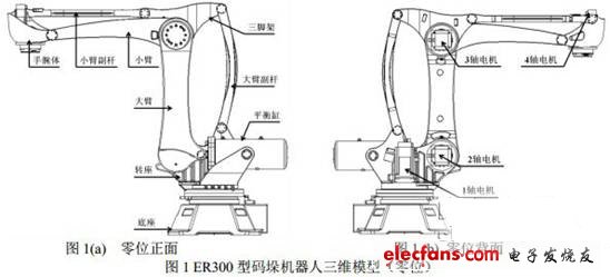
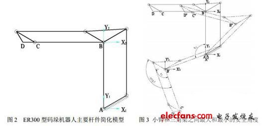
The three-dimensional model in Figure 1 is further simplified as a rod connection (1 axis and balance cylinder are omitted). As shown in Figure 2, point A is the robot's 2 axis, and point B is the composite hinge. The boom sub-bar, a parallelogram structure connected in series with the forearm and the boom sub-bar, keeps the rotation axis of the wrist body always perpendicular to the ground during the movement, so that the position of the center D of the wrist body relative to the point C of the arm end remains change.
In addition, the ER300 robot adopts the installation method of fixing the 3-axis motor and the reducer on the tripod. This kind of connection makes the tripod and the boom sub-bar bear the torque M of the three arms about the 3-axis of the arm, wrist body and load, but the arm does not rotate with the arm, which greatly simplifies the movement of the robot Way and control method.
In view of the fact that the ER300 palletizing robot does not have complicated coupling motion, this paper does not use the traditional DH method for calculation. In order to study and calculate the reachable space of point D, the origin O0 of the global coordinate system is fixed at the intersection of the 1 axis and the ground, Y0 coincides with the 1 axis, and the remaining local coordinate systems are shown in Figure 2
In the global coordinate system, the conversion relationship between the coordinates of each joint point and the joint rotation angle is as follows:
Among them, R and H are the radius of rotation of 1 axis and the height of the base; L2 and L3 are the length of the boom and the arm; respectively, the angle of rotation of the boom relative to the Y1 axis, and the angle of rotation of the arm relative to the X2 axis. The rotation is positive; S is long.
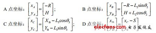
In the zero position, the rotation range of the 2-axis and 3-axis are respectively. In order to protect the parallelogram structure at the end of the palletizing robot and prevent interference between the rods, ER300 is the safety angle set between the arm and the tripod (as shown in the figure 3). Therefore, the relationship between the rotation angle range of the forearm and the rotation angle of the forearm is:
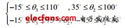
Figure 3 shows the maximum and minimum safety angle between the arm and the tripod at two extreme positions on the 2-axis.
3 ADAMS motion simulation
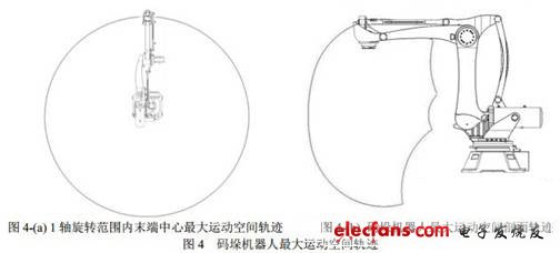
ADAMS is a classic software that simulates the kinematics and dynamics of mechanical systems. In order to further demonstrate the movement space form of the palletizing robot, this article imports the three-dimensional model of the palletizing robot established by solidworks into ADAMS, and simulates the movement of the robot. Its maximum movement space profile trajectory is shown in FIG. The maximum motion space structure of the stacking robot.
After completing the simulation in Figure 4- (b) above, the 2-axis and 3-axis MoTIon drive angular velocities are shown in Figure 5:
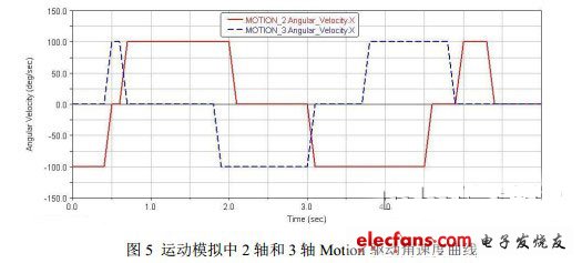
It can be further seen in conjunction with FIGS. 4 and 5 that the specific structure of the ER300 robot makes it without complex coupling movement between the large and small arms during the movement process, simplifying the robot movement mode and control method.
The simulation results also show that during the movement of the robot, the boom sub-bar is subjected to a large pulling force at certain positions. It can be seen from theoretical analysis that when the torque M is constant, the pull force F of the boom sub-bar is inversely proportional to the force L about the 3-axis, so that at some specific positions, a small change in the force L will cause a large change in F . Therefore, in the robot design process, the strength and rigidity of the boom sub-bar and its components must be fully ensured to ensure the reliability and accuracy of the robot.
4 Numerical calculation of motion space
In order to accurately calculate and verify the reachable space of the palletizing robot, this article uses the basic parameters of the ER300 palletizing robot: R = 400mm, H = 835.5mm, L2 = 1250mm, L3 = 1300mm, W = 225mm. Use matlab programming calculation And the theoretical motion up to space section of the D point of the wrist body of the palletizing robot is drawn, as shown in Figure 6:
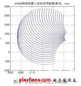
The calculation results show that at that time, the point D at the end of the robot reached the highest point of the maximum working space; at that time, the point D at the end of the robot reached the lowest point of the maximum working space; at that time, the robot reached the maximum arm position, these three positions determine the palletizing robot The maximum stacking range of the main body in vertical and horizontal directions is an important parameter to measure the working performance of the stacking robot.
Comparing with the calculation results of ADAMS simulated motion track point coordinates, and considering the error factors of ADAMS simulated trajectory solution accuracy and discrete calculation methods, the simulation results and theoretical calculation results are basically consistent with the design goals, and both can reach the maximum arm span of 3175mm, 3104mm height requirement in Y direction.
Compared with ABB's IRB660-180, KUKA's KR180-2PA and KAWASAKI's ZD130S working space, the results show that under the basic parameters of ER300, the motion space basically overlaps with the above similar robots, which can meet the general needs of the market (arm spread, code Stack height, etc.).
5 Conclusion
In this paper, through the analysis of the ER300 palletizing robot mechanism, it shows the bar relationship and movement form of the general palletizing robot; while explaining the advantages of this mechanism, it also points out the problems that need to be paid attention to in the design process; simulation And calculated the maximum movement space of the palletizing robot, and verified the movement form of the robot.
In this paper, the mechanism and motion analysis of the palletizing robot provide a certain theoretical basis and practical reference for the research and development of this type of robot.
Brushed Dc Motor,Dc Brushed Motor,Brushed Rc Motors,High Torque Brushed Dc Motor
Changzhou Sherry International Trading Co., Ltd. , https://www.sherry-motor.com