![<?echo $_SERVER['SERVER_NAME'];?>](/template/twentyseventeen/skin/images/header.jpg)
1 Introduction
11.1V lithium battery is commonly used in metric airplanes such as ducted machines, fixed wings, helicopters, etc. It has stable discharge and wide operating temperature; allows large charging current and fast charging speed, and can be filled in only 1~2 hours; no memory Effect; low self-discharge rate, long storage life; high energy, high storage energy density; high output voltage (the rated voltage of a single-cell lithium battery is generally 3.6V, while the voltage of a single-cell Ni-MH and Ni-Cd battery is only 1.2V) Etc. However, lithium batteries also have a delicate side in use. To prevent overcharging when charging a lithium battery, if the charging voltage is higher than the specified voltage or the charging current is greater than the specified current, the lithium battery may be damaged or discarded. In the case of overcharging, the temperature of the excess lithium battery rises, and the electrolyte decomposes to generate a gas, causing the internal pressure to rise to cause self-ignition or breakage. Generally, the termination charge voltage of a single-cell lithium battery is 4.2V, the accuracy is controlled within ±1%, and the charging current is not more than 1C (C stands for charge and discharge rate, 1C means that the battery is just within 1 hour, fully charged or discharged. Required rate). Lithium batteries should also be protected from excessive discharge during use. Excessive discharge can result in poor battery characteristics and durability, and the number of chargeable cycles is reduced. Generally, the discharge current is required to be no more than 2C, and the termination discharge voltage is controlled to be about 2.4 to 2.7V.
2. Charging circuit structure design analysis
The lithium battery needs to control its charging voltage and charging current during charging and accurately measure the battery voltage. The charging process is divided into four stages according to the lithium battery voltage. Each stage needs to be charged with different voltages and currents. The state of each stage is illustrated by taking a single-cell lithium battery as an example. Phase one is pre-charging, first pre-charging the lithium battery with a small current of 0.1C, and going to the next stage when the battery voltage is ≥2.5V. In the second stage, the constant current is charged, and the lithium battery is quickly charged with a constant current of 1 C. When the battery voltage is ≥ 4.2 V, the process is shifted to the next stage. Phase III is constant voltage charging, gradually reducing the charging current, ensuring that the battery voltage is constant = 4.2V, and when the charging current is ≤ 0.1C, it goes to the next stage. Phase 4 is trickle charging. After the constant voltage charging is finished, the battery is basically full. In order to maintain the battery voltage, the battery can be recharged with a current of 0.1 C or less, and the charging process of the lithium battery ends.
3. The hardware circuit design of the Charger
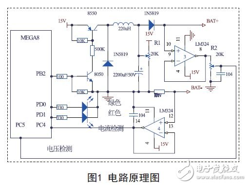
The system mainly comprises a microcontroller, a voltage detecting circuit, a current detecting circuit, a battery state indicating circuit and a charging control circuit, and the circuit schematic diagram is shown in FIG. 1 .
3.1 master chip
This system uses ATmega8 as the control core.
ATmega8 is a high performance, low power microprocessor for AVR. It uses an advanced RISC architecture with 130 instructions. Most of the instruction execution time is a single clock cycle. It has 32 8-bit general-purpose working registers and operates up to 16MIPS at 16MHz. It only requires two clock cycles of hardware multipliers. 8K bytes of in-system programmable Flash; optional Boot code area for independent lock bits; 512 bytes of E2PROM; 1K bytes of on-chip SRAM; two with independent prescaler 8-bit timer/counter; Programming I/O port; 8-channel 10-bit ADC; three-channel PWM; real-time counter RTC; byte-oriented two-wire interface; two USART interfaces; SPI interface for master/slave mode; on-chip watchdog Internal resources such as timers; on-chip analog comparators.
3.2 voltage detection circuit
Since the reference voltage of the ADC of ATmega8 is set to 3.072V, and the voltage of the battery can be as high as 12.6V during charging, the battery voltage needs to be scaled down before being sent to the ADC port of ATmega8 for acquisition.
The circuit consists of a phase-inverter and a 20K adjustable resistor. After the battery voltage is input to the in-phase unit consisting of LM324, it is isolated and buffered by the inverter and output to a 20K adjustable resistor. The adjustable resistor is used to input the input to the ATmega8. The voltage at the ADC port is one-fifth of the battery voltage.
Industrial Power Supply,Universal Ac Power Adapter,Industrial Dc Power Supply,Industrial 12V Power Supply
Ninghai Yingjiao Electrical Co., Ltd. , https://www.yingjiaoadapter.com