![<?echo $_SERVER['SERVER_NAME'];?>](/template/twentyseventeen/skin/images/header.jpg)
RF cable can be customized for other specifications
Industrial Router Crystal 3.2*2.5mm 3225 26M (26.000MHZ) 12PF 10PPM 20PPM 30PPM
Photocoupler
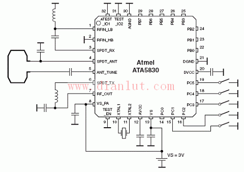
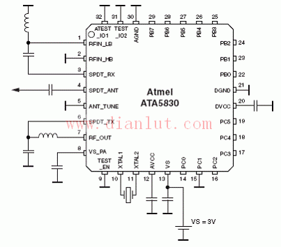
 The following is the circuit diagram of [ATA5830 application circuit diagram]
 The ATA5830 is a general purpose, highly integrated, low power UHF ASK/FSK RF monolithic transceiver that includes the RF section, digital baseband and AVR microcontroller cores, and the core is a low power CMOS 8-bit MCU with enhanced RISC architecture. In the ISM band, the frequency range is 310MHz-318MHz, 418MHz-477MHz and 836MHz-928MHz, data rate 0.5k to 20kBit/s Manchester, working voltage 1.9V-3.6V and 4.5V-5.5V, working temperature –40°C to + 105 ° C, mainly used in RKE, TPMS, remote start and control systems, and intelligent RF applications.
Typical 3V application circuit diagram of ATA5830 using loop antenna
ATA5830 typical 5V application circuit diagram

ATA5830 typical 3V application circuit diagram (responsible editor: circuit diagram)
Breaker Rccb,Rccb Breaker,Rccb Circuit Breaker,Circuit Breaker Rccb
ZHEJIANG QIANNA ELECTRIC CO.,LTD , https://www.traner-elec.com