![<?echo $_SERVER['SERVER_NAME'];?>](/template/twentyseventeen/skin/images/header.jpg)
The CD4047 consists of an optional non-stationary multivibrator that can be used as a forward/reverse edge-triggered monostable multivibrator with retriggering and external counting options. Inputs include TR+, TR-, AST, AST, RET, and CR. The buffer outputs are Q, Q, and QQSC. In all modes of operation, the device should have an external capacitor (C) between the CEXT and REXT /CEXT terminals and an external resistor (R) between the REXT /CEXT and REXT terminals. When AST is high, it is an unsteady mode of operation, and the square wave period at the Q and Q outputs is a function of R and C. The AST's original pulse or AST back-pulse allows the circuit to be used as an optional multi-vibrator. The output stage of the QQSC is half of the output of the Q terminal, but the output does not guarantee a 50% duty cycle, in monostable mode. When TR- is low, the leading edge pulse applied to the TR+ input is the positive edge trigger; likewise, when TR+ is high, the trailing edge pulse added to TR- is the reverse edge trigger. The pulse width of the input pulse can be any value relative to the output pulse. Add a common pulse to the RET and TR+ inputs and the multivibrator can be retriggered (only on the leading edge). The output pulse width can be extended with an external counter IC.
The CD4047 is available in 14-lead multilayer ceramic in-line (D), sealed ceramic dual in-line (J), plastic dual in-line (P) and ceramic chip carrier (C) packages.
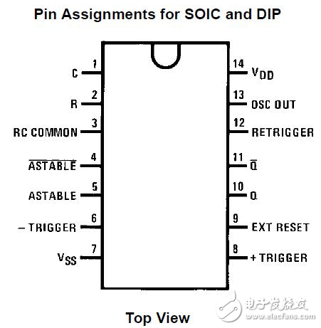
Figure 1 is a pin diagram of the CD4047
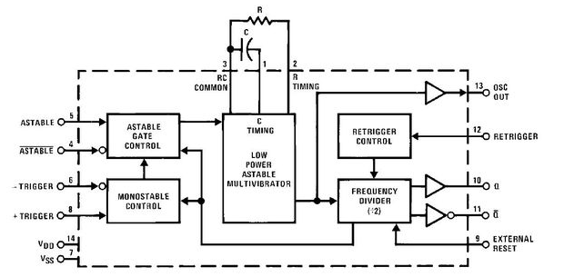
Figure 2 is the internal function diagram of CD4047
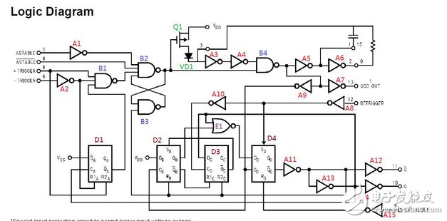
Figure 3 is the internal logic diagram of CD4047
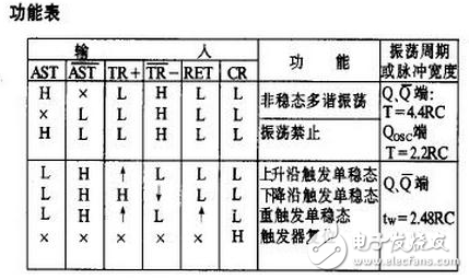
Figure 4 is a function table of the CD4047.
Cd4047 pin function description1, 1 pin C, external capacitor C, and R constitute an oscillating network.
2, 2 pin R, external resistor R, and C constitute an oscillating network.
3, 3 pin RC COMMON, the common end of the RC oscillation network, connect one end of R to one end of C, and connect this point to the 3 pin.
4, 4 pin \ASTABLE, the enable end of the non-stationary multivibrator, active low, the same as the 5-pin function.
5, 5 pin ASTABLE, the enable end of the non-stationary multivibrator, active high, the same as the 4-pin function.
6, 6 pin - TRIGGER, the trigger signal of the monostable multi-trigger trigger, the falling edge trigger, the same as the 8-pin function.
7, 7 pin Vss, power ground, generally connected to the reference ground of the power supply.
8, 8 pin + TRIGGER, the trigger signal of the monostable multi-trigger trigger, triggered by the rising and falling edge, the same function as the 6 pin.
9, 9 pin EXT Reset, external reset signal, active high, if valid, the output of CD4047 will be reset.
10, 10 pins \ Q, output, complementary to 11 pin Q, phase difference 180 °
11, 11 pin Q, output, complementary to 10 pin \Q, phase difference 180 °
12, 12 pin RETRIGGER, repeated trigger input, applied in the repeat trigger mode, generally connected 12 pin and 8 pin.
13, 13 pin, OSC OUT, oscillating waveform output, the frequency is 2 times the frequency of the output signal of 10 pins and 11 pins.
14, 14 pin, VDD, chip power supply, the chip's power supply range is: 3-15V
Jiangsu Acrel Electrical Manufacturing Co., LTD. , https://www.acrel.com.pk