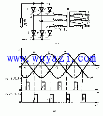
In a three-phase controlled rectifier circuit, choosing the correct synchronization power supply for the triggering circuit is crucial. Only when the synchronization source is properly selected can each thyristor trigger in sequence at the right time. The selection of the synchronization power supply depends on three main factors: (1) the configuration of the rectifier circuit and the winding connection of the rectifier transformer; (2) the winding connection of the synchronization transformer; and (3) the phase relationship between the synchronization voltage and the trigger pulse in the circuit. Let's take the three-phase full-bridge rectifier as an example to explain how to choose the synchronization power supply.
When the phase control angle α is 0°, the six thyristors T1 through T6 must have their trigger pulses arranged in a specific order, as shown in Figure 1(b), to ensure that the trigger pulses are synchronized with the main power supply. This synchronization is achieved by selecting the proper phase of the synchronization voltage, provided the frequencies match.
Since different trigger circuits may require different phases of the synchronization voltage, let's use the example of a sawtooth wave trigger circuit with a synchronous voltage to illustrate the process. 
As shown in Figure 1, the zero crossing of the synchronization voltage uT marks the start of the sawtooth wave in this type of circuit. To ensure that the phase shift range of the pulse falls within the area where the thyristor can be triggered, the start of the sawtooth wave must align with the α = 0° point of the thyristor. Therefore, the synchronization voltage for the thyristor T1 connected to the main circuit’s ua phase should be set 150° ahead of the ua signal, so that the trigger pulse for T1 appears at 30° of the ua waveform.
Based on this relationship, once the main transformer’s connection mode is determined, the connection of the synchronization transformer and the synchronization voltage for each phase trigger circuit can be further defined. By analyzing the vector diagram of the rectifier and synchronization transformers, it becomes clear that the synchronization voltage for the T1 thyristor’s trigger circuit should lead the ua voltage by 150°. If the main transformer’s configuration or the trigger circuit changes, the synchronization transformer connections and the synchronization voltages for each trigger circuit must also be adjusted accordingly to ensure the trigger circuit starts at the natural commutation point of the main power phase voltage.
Determining the initial phase is also important. In many applications, the drive system must start at zero when the main and control circuits are powered on. When the control voltage is zero, the output voltage of the controlled rectifier device should also be zero. This point is referred to as the initial phase of the trigger pulse. The initial phase angle depends on the configuration of the main circuit and the load characteristics. For example, in a three-phase half-controlled bridge rectifier, Ud equals zero when α is 180°. In a three-phase full-bridge rectifier with a resistive load, Ud is zero when α is 120°. Under large inductive loads, where the current remains continuous, Ud is zero when α is 90°. If the inductive load is insufficient, the initial phase angle will fall between 90° and 120°.
To achieve the desired initial phase when the control voltage UK is zero, an offset voltage is added to the trigger circuit. Adjusting the magnitude of this offset voltage allows the initial phase of the trigger pulse to be fine-tuned. The polarity of the offset voltage is always opposite to that of the sawtooth wave, ensuring stable and accurate triggering of the thyristor.
Custom Made Length 35 cm USB C to iOS Phone Cable Cord, Right Size Angle for DJI Mini 2/3 Pro/Mavic Air 2 / Mavic 3 Remote Controller & iPhone, iPad Devices
Compatible for DJI Mini 2, Maivc 3 pro & Mavic Air 2 Remote Controller,works for iPhone/iPad Device
Perfect length (35cm) and right angle Connecting when you use tablet holder for drones with the devices.
Unique 90 Degree Plug Provides a slim fit in narrow spaces.
This cable can transfer data and charger with all iOS Device
Custom Requirements
In addition to the off the shelf offerings Technical Cable Applications skilled specialists are ready to help with any custom cable assembly requirements you might have. UCOAX stocks cables by the thousands and can custom build anything not on hand. Please contact the UCOAX Technical Sales Team for assistance with all your cable assembly needs.
Drone Cable,Drone Battery Charger Cable,Drone Cables,Drone Controller Cable
UCOAX , https://www.ucoax.com
![<?echo $_SERVER['SERVER_NAME'];?>](/template/twentyseventeen/skin/images/header.jpg)