![<?echo $_SERVER['SERVER_NAME'];?>](/template/twentyseventeen/skin/images/header.jpg)
The recently approved draft of the 802.11n standard presents a significant opportunity for existing wireless local area network (WLAN) devices and chipset manufacturers. As this standard matures, it will enable companies to deliver improved performance across a wide range of wireless Internet access products, opening up new markets in audio and video distribution. However, the integration of multiple input and multiple output (MIMO) radio frequency capabilities poses challenges, especially as the industry continues to push for smaller form factors, lower power consumption, and reduced costs. This article explores the design challenges associated with RF MIMO solutions, highlights key performance metrics, and explains how MIMO front-end modules can help developers overcome these obstacles.
The Advantages of 802.11n
Compared to earlier wireless standards, 802.11n offers several compelling benefits. It supports data rates between 200 and 400 Mbps, making it suitable for home networking, high-speed downloads, and media streaming. Additionally, it provides a 20% to 30% increase in signal range over previous 802.11a/b/g standards, along with backward compatibility. This means users can seamlessly use the same devices in different environments—home, office, or on the go—without losing connectivity, even if the performance is slightly reduced compared to full MIMO setups. 802.11n client cards automatically switch between 802.11n and older standards based on availability. One of its most significant advantages is that it operates on the same frequency bands (2.4 GHz and 5 GHz) as the existing standards, allowing manufacturers to leverage existing production technologies and components, reducing costs and accelerating deployment of high-speed networks.
Technical Challenges of RF Design
Error Vector Magnitude (EVM) plays a critical role in determining overall throughput and system performance. A well-designed front-end module should maintain an EVM below 3% (-30 dB) at rated output power. In MIMO systems, better linearity is essential because accurate channel modeling depends on a strong and clean transmitter. If the EVM from the transmitter is poor, the performance of the MIMO system can be significantly degraded. However, EVM alone isn't enough; the EVM characteristics of the front-end module should closely follow an exponential curve, as shown in Figure 1a, rather than having a "sweet spot" like in Figure 1b. Modules with a "sweet spot" must operate at a specific power level to meet performance specifications. Deviating from this point increases EVM and reduces throughput. Moreover, this optimal point can shift due to process variations, voltage fluctuations, matching circuitry, and temperature changes, leading to inconsistent performance. Such modules may not meet minimum performance requirements, making them unsuitable for applications that demand reliability.
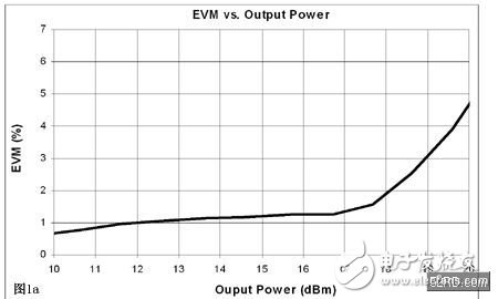
Front-end modules with exponential EVM curves offer greater flexibility, especially when designing for global markets with varying regulatory standards. A design optimized for the highest output power can still perform well in regions with lower power limits. However, modules with a "sweet spot" like Figure 1b are less adaptable. Regulatory bodies sometimes define total power as the sum of all antennas, which may require compensating 3–6 dB to meet compliance. Even if the module can support high output per antenna, this compensation could impact performance. For single-antenna 802.11a/b/g devices, users expect maximum transmit power. Operating under different power levels with a non-exponential EVM curve can lead to performance issues, as discussed earlier.
Dimensions
As product sizes continue to shrink, wireless standards become more complex, requiring more circuitry and higher power consumption. This trend poses a major challenge for RF designers. The latest PCIE mini card, for example, is only half the size of the dominant mini PCI card used in current WLAN designs. These traditional designs typically include one RF transmit and one RF receive link. However, MIMO-based 802.11n applications require two transmit and two receive links, as illustrated in Figure 2. Given the number of components and the need for keep-out areas during manufacturing, integrating such circuits into a small form factor is extremely difficult. Fortunately, MIMO front-end modules offer a solution by providing a fully tested, compact RF solution that integrates all necessary circuitry from the transceiver to the antenna, simplifying design and improving performance in space-constrained applications.
24HR Electronic Timer socket with photocell.
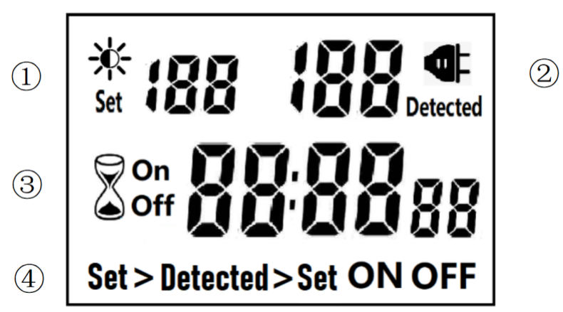
â‘ Light intensity setting
â‘¡ Light intensity detection
â‘¢ Countdown Timer ON & OFF
â‘£ 4 MODES:
Set > Detected: When the light intensity detection value is less than the set value, switch ON or OFF.
Detected > Set: When the light intensity detection value is greater than the set value, switch ON or OFF
ON : Always ON
OFF : Always OFF
NOTED:
1. The light intensity displayed by this machine is not the standard light intensity value (Lux), only the relative light intensity value.
2. The light intensity value is affected by the placement position and direction. Please determine the position first and then set it according to the actual light intensity detected. If you change the position or change the orientation, you need to reset the light intensity setting value suitable for the new position.
3. This product has built-in rechargeable battery. If it is not connected to AC for a long time, you need to connect the power supply to charge until the LCD can display normally.
MANUAL OPERATION
1. Press [UP" or [DOWN" to set the LUX value.
2. Press the [SET" key to start setting, and the P1 settable items will be flashed.
3. Press [UP" or [DOWN" to adjust the value.
4. Press [SET" key again to exit setting or enter next setting for countdown timer.
5. Repeat the [SET" key to start setting, and the P2 & P3 settable items will be flashed.


6. Press the [FUN" key to switch the working state in the following:
Set > Detected -> Detected > Set -> ON -> OFF
Set > Detected: Automatically switches when the detected ambient light intensity is darker than the set value
Detected >Set: Automatically switch when the detected ambient light intensity is brighter than the set value
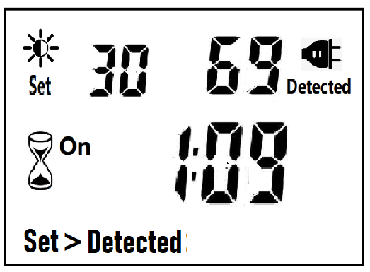
When the brightness meets the setting conditions, the countdown starts as below:
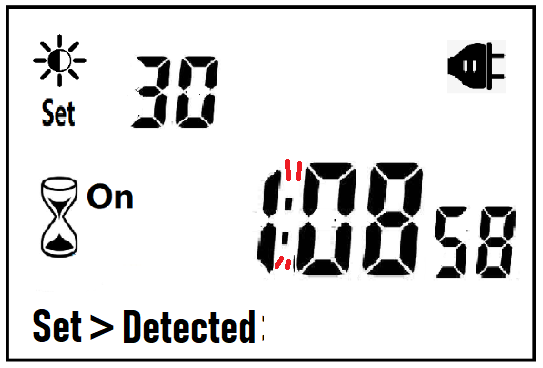
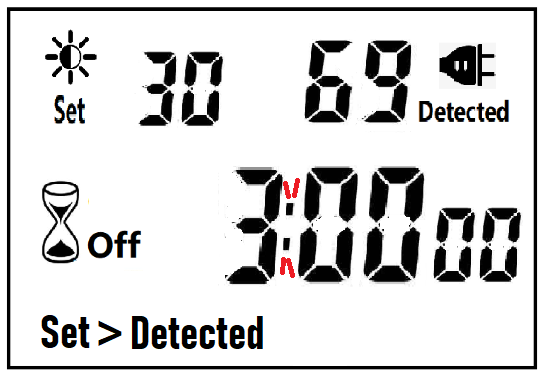
Note:when the countdown is ON, the detected value is not displayed.
When the brightness does not meet the setting conditions, the countdown stops and waits:
After the countdown ON is reduced to 0, the countdown OFF starts immediately and the power is OFF.
After the countdown OFF is reduced to 0:
A. If the light intensity meets the set conditions, a new round of countdown will be started;
B. If the light intensity does not meet the set conditions, keep the power off and wait for the light to meet the conditions before turning on automatically.
NOTE:
1. If the power is cut off while the countdown is running, the countdown will be terminated immediately and the relay output will be off. After the power is turned on again, a new round of brightness detection will start.
2. Modifying the brightness value in the countdown operation will not affect the current countdown operation. After the off time of the current countdown, the new brightness setting value will take effect.
3. In the countdown on operation, change the setting value of the countdown on, this countdown will still be timed according to the original setting value; the new setting value will take effect when the next countdown on starts.
4. In the countdown off operation, change the setting value of countdown off, this countdown will still be timed according to the original setting value; the new setting value will take effect when the next countdown off is started.
NOTE: the brightness setting value, countdown ON or countdown OFF, any one of which is equal to 0, cannot be switched ON or OFF automatically.
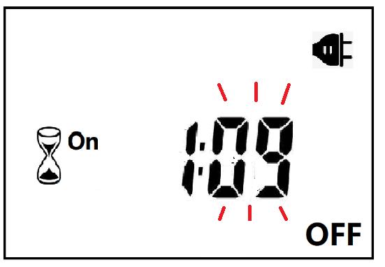
Manual Control
When ON or OFF is displayed, it means that the power supply remains ON or OFF, as shown in the figure below:

Power Detection and Standby Mode
With AC power supply, the icon ![]() lights up and works normally.
lights up and works normally.
When there is no AC power supply, the icon ![]() goes out, the brightness is not detected at this time, and the system enters the standby mode.
goes out, the brightness is not detected at this time, and the system enters the standby mode.
Photocell Timer, photocell timer socket, photocell sensor, photocell sensor socket, sensor plug, sensor switch socket, digital photocell timer, digital sensor timer
NINGBO COWELL ELECTRONICS & TECHNOLOGY CO., LTD , https://www.cowellsocket.com