![<?echo $_SERVER['SERVER_NAME'];?>](/template/twentyseventeen/skin/images/header.jpg)
**1. Introduction**
As a core device of microcomputer technology, the Programmable Logic Controller (PLC) has become an essential tool in various industrial sectors such as manufacturing, metallurgy, chemical processing, and energy. Known for its high reliability, strong anti-interference capability, simple structure, and lightweight design, PLC is specifically developed for digital operations in industrial environments and process control. With rich internal timer resources and strong adaptability to different working conditions, PLC has proven to be an ideal choice for traffic light control systems. Although widely used in industrial automation, its application in traffic control is still emerging. PLC offers advantages like easy programming, convenient debugging, and efficient operation, making it gradually replace traditional microcontroller units (MCUs) in traffic signal systems. This paper presents a study on the design of a traffic light control system using the Siemens S7-200 PLC.
**2. Control Requirements for Traffic Lights**
The schematic diagram of the traffic light control system is illustrated in Figure 1.
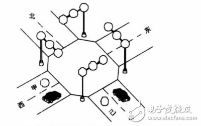
Figure 1: Schematic Diagram of Traffic Light Control
The traffic light system must meet the following requirements: 1. The system is controlled by a start switch. When the switch is activated, the traffic lights operate normally, with the south and north red lights on, and the green light illuminated. When the switch is turned off, all lights are deactivated. 2. The south red light remains on for 25 seconds, while the east-west green light stays on for 20 seconds. After 20 seconds, the east-west green light turns off, and the yellow light comes on for 3 seconds. Then, the yellow light turns off, and the red light is activated. At the same time, the north-south green light turns on. 3. The north-south red light remains active for 30 seconds, followed by the green light staying on for 25 seconds. Then, the green light flashes for 3 seconds before turning off. Simultaneously, the north-south yellow light is activated for 2 seconds and then turns off. 4. The entire sequence repeats continuously to ensure smooth traffic flow. **3. System Timing Diagram** Based on the control requirements, this system is a sequential logic control system. To facilitate software and hardware design, a timing diagram was created. Figure 2 shows the state timing diagram of the traffic light system.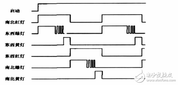
Figure 2: State Timing Diagram of Traffic Lights
**4. System Hardware Design** To meet the control requirements, the Siemens S7-200 series PLC was selected as the central controller. This model provides sufficient I/O points and reliable performance for traffic light applications. **4.1. PLC I/O Point Assignment** The system requires one input point for the start button. For output signals, there are two sets of indicator lights for the east-west and north-south directions, along with vehicle running indicators. To reduce the number of output points, a parallel output method was used, as lights of the same color operate in the same direction. Therefore, the system needs 1 input point and 8 output points, all of which are digital signals. The I/O point assignment is listed in Table 1.Table 1: PLC I/O Point Allocation
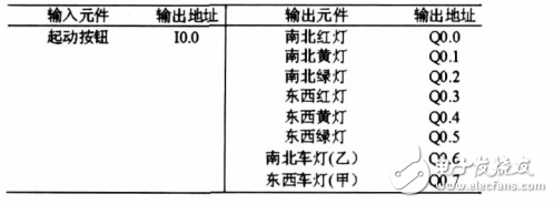
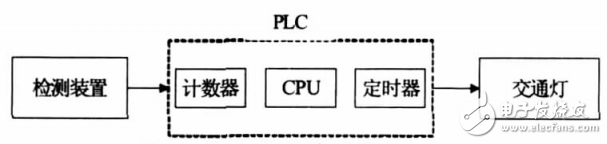
Figure 3: System Hardware Structure
Piezo Transducer,Piezo Audio Transducer,Piezoceramic Transducer,Piezo Pressure Transducer
NINGBO SANCO ELECTRONICS CO., LTD. , https://www.sancobuzzer.com