![<?echo $_SERVER['SERVER_NAME'];?>](/template/twentyseventeen/skin/images/header.jpg)
The LED lighting industry is rapidly evolving, and traditional lighting solutions are being increasingly replaced by more efficient and advanced LED technologies. As this transition accelerates, the power demands on LED drivers continue to grow. Maintaining high current detection accuracy becomes more challenging as the current increases, especially when efficiency must not be compromised. Therefore, modern LED drivers need to ensure precise current sensing while efficiently delivering power to multiple independent LED loads, supporting parallel connections with accurate current distribution.
Some high-power LEDs come with specific mechanical and electrical design considerations. For example, their positive terminals are often electrically connected to the thermally conductive rear housing. In a conventional buck regulator-based LED driver, thermal management is typically achieved by cooling the chassis. However, this setup creates an electromechanical challenge, as the rear panel must have good thermal conductivity to the heat sink but also remain electrically isolated from the chassis if there's a voltage difference. Since LED manufacturers face limitations in changing production processes or packaging, the LED driver itself must adapt to these constraints.
One solution is to use a four-switch positive buck-boost configuration, although it introduces additional complexity and cost. Alternatively, the negative output buck-boost topology offers a simpler approach by using only one set of switching MOSFETs. This allows the positive terminal to be directly connected to the heat sink, eliminating the need for extra isolation components and simplifying the mechanical design of the system.
To meet demanding performance requirements, the LT3744 can be configured as a synchronous buck or negative output buck-boost controller, capable of driving LED loads with continuous currents exceeding 20A. It supports a wide input voltage range from 3.3V to 36V. When used as a buck converter, it regulates LED current from 0V up to the supply voltage range. As a negative output buck-boost converter, it accurately controls LED current over an output voltage range of 0V to 20V.
The LT3744 offers high analog current regulation accuracy across the full scale, with 3% accuracy at full scale and better than ±30% at 1/20 scale. It features three independent analog and digital control inputs, along with three compensation and gate drive outputs, making it suitable for various LED configurations. By separating inductor current sensing from LED current sensing, the LT3744 can be flexibly configured as either a buck or a negative output buck-boost controller. All input signals are referenced to board ground (SGND), eliminating the need for complex level shifters and simplifying system design.
In a negative output buck-boost configuration, the total forward voltage of the LED string can exceed the input supply voltage, enabling high-voltage LED strings to be driven by a low-voltage power source. Additionally, the LT3744 can be easily paralleled to handle large LED pulse or DC load currents, making it ideal for applications requiring high power density and efficient thermal management.
High Accuracy Current Detection
The LT3744 includes a high-accuracy current-regulated error amplifier, allowing precise analog dimming down to 1/20 of the total current range. This feature is essential in applications where digital PWM dimming range is limited or where a very wide dimming range is required. For instance, with a 100Hz PWM dimming frequency and a 1MHz switching frequency, the LT3744 achieves a 1250:1 PWM dimming ratio, which can be combined with 20:1 analog dimming to extend the overall dimming range to 25,000:1.
Figure 1 illustrates the production consistency of the LT3744’s offset voltage as a function of temperature when the analog control input is 0V. With a typical device count of 380, the low offset of the error amplifier ensures a loop accuracy of ±10% at 1/20 scale analog dimming. Figure 2 shows the distribution of the regulated voltage across multiple LED current sense pins when the control input is 1.5V. The full-scale accuracy is better than ±3%, equivalent to ±1.8mV at a 60mV full-scale regulation level.
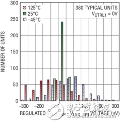
Figure 1: Typical offset voltage of the LED current-regulating amplifier in the LT3744 is ±300μV with VCTRL = 0V
NUMBER OF UNITS: Number of devices
380 TYPICAL UNITS: Typically 380 devices
REGULATED VLED_ISP – VLED_ISN VOLTAGE: Stable VLED_ISP – VLED_ISN voltage
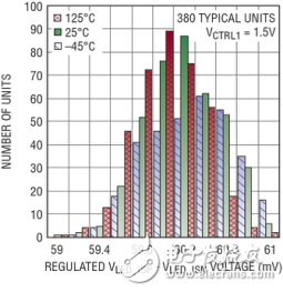
Figure 2: Typical accuracy of the LED current regulation loop is ±1.7% at full scale current and VCTRL = 1.5V.
Flicker Free Performance
One of the most critical performance metrics for LED drivers is the speed at which the LED current recovers during PWM dimming. In the initial few switching cycles after the PWM signal turns on, the driver's performance significantly impacts the final product quality. The LT3744 uses proprietary PWM, compensation, and clock synchronization techniques to deliver flicker-free operation, even when driving LEDs at 20A.
Figure 3 shows the LED current recovery over a 5-minute period when a 20V current is applied to a red LED with a 12V supply. The switching frequency is 550kHz, the inductor is 1μH, the PWM dimming frequency is 100Hz, and the turn-on time is 10μs (a 1000:1 dimming ratio). The graph displays approximately 30,000 dimming cycles without any jitter in the switching waveform, with each recovery cycle being consistent.

Figure 3: LT3744 provides flicker-free LED dimming
10V/DIV: 10V per division
5-MINUTE PERSISTENCE: lasts 5 minutes
KW3-Basic Micro Switch-Lever Type
Micro Switch,KW3 Basic Micro Switch,Lever Type Switch
Ningbo Jialin Electronics Co.,Ltd , https://www.donghai-switch.com