![<?echo $_SERVER['SERVER_NAME'];?>](/template/twentyseventeen/skin/images/header.jpg)
1 Preface
For an emerging product, the development of the product itself always precedes the product standard and testing method. Although the standards and testing methods of the products cannot be prior to the development of the products, the standards and testing methods of the products should be as close as possible to the progress of product design and development, because the standard of the products and the method of testing the testing process itself is the product development. Review and summary of the process, as long as the conditions are basically mature, the more timely the product standards and testing methods are formulated, the more blind the product development process can be. The LED lighting industry has developed to the present, and we have basically come back to the review and summary of LED lighting product standards and testing methods.
2 Status and improvement methods of photoelectric parameters and detection methods of LED modules
2. 1 Traditional LED module detection method
At present, there are two main methods for detecting traditional LED modules. The first one is to use pulse measurement method, which is to fix the illumination LED module on the measuring device (such as the measuring position of the integrating sphere, etc.), using a pulse constant current Power Supply and Simultaneously measuring the synchronous linkage of the spectrometer, that is, simultaneously emitting a pulse current of a constant current of several tens of milliseconds to several hundreds of milliseconds to the LED, simultaneously opening the shutter of the instantaneous measuring spectrometer, and performing light parameters (light flux, light color parameter, etc.) emitted by the LED Quick detection, meanwhile, also synchronously collect parameters such as forward voltage drop and power of the LED. Because the junction temperature of the LED is almost equal to the room temperature during the detection process, the light effect of the measurement result is high, and the light color and electrical parameters are significantly different from the actual use conditions, which are generally produced by LED chips (devices). The rapid detection method adopted by the quotient is not comparable to the state in which the LED is actually applied in the final lighting fixture.
The second test method is to install the LED module on the detection device, possibly with a fixed heat sink (may also have a base temperature control function), apply the claimed working current to the LED, and be detected by the traditional illumination source. The effect of the method is also to wait until the LED reaches thermal equilibrium before starting to measure its photoelectric parameters. This method seems to be more rigorous, but in fact, its thermal equilibrium conditions and working conditions are still not well correlated with the state of such LEDs into the final lighting fixture, so the measured photoelectric parameters and future practical applications The parameters of the state are still not comparable. GB/T24824-2009 /CIE 127-2007 has been promulgated in the NEQ "Measurement Method for Basic Performance of LED Modules for General Lighting" standard, which is stipulated in this respect: "The LED module should work in thermal equilibrium during test or measurement. Under the monitoring of the ambient temperature, it is best to monitor the operating temperature of the LED module itself to ensure the reproducibility of the test. If it is possible to monitor the LED module junction voltage, the monitoring junction voltage should be preferred. Otherwise, the LED module should be monitored. Specify the temperature of the temperature measurement point."
It can be seen that measuring the photoelectric parameters of the LED module under the condition of monitoring the junction voltage is the preferred solution to ensure the reproducibility of the detection. However, the standard does not specify the light, color and electrical parameters of the LED module under the condition of simulating the actual use of the junction temperature.
2. 2 LED module measurement method improvement
As we all know, the light and electrical parameters of LEDs are closely related to the junction temperature of the LEDs. The same LED product will have different junction temperatures, which will cause the same LED light, color and electrical parameters. The apparent inconsistency of the measurement results, so the measurement of the photoelectric parameters of the LED should first be considered under the conditions of the set operating junction temperature. In addition, because of the difference in packaging process and materials, the claimed maximum operating junction temperature is significantly different. In order to ensure the high efficiency and longevity of LED lighting products, the actual working junction temperature of LED should be significantly lower than the highest working junction temperature. . For example, at present, a large number of LED packaging methods and technologies are used, and in the face of LED illumination, there are coating layers of polymer silica gel and phosphor. Practice has proved that for such LED lighting fixtures, the time to 70% of the lumen maintenance rate should be ≥ 60,000 hours, and the operating junction temperature must be kept below 70 ~ 75 °C. From the perspective of improving light efficiency and service life, it is better to keep the working junction temperature of LEDs below 60 °C, but in terms of the shape, volume and cost performance of lighting fixtures, it should be controlled to achieve the desired light efficiency and Based on the service life, it is most suitable to control the maximum operating junction temperature of the LED at 70 to 75 °C. In order to make the detection of the light, color and electrical parameters of the LED and its module as close as possible to the junction temperature of the actual application, it is necessary to solve how to measure the junction temperature of the LED and to perform light, color and electricity at this junction temperature. Detection of parameters.
(1) At present, the LED junction temperature measurement methods are:
1 Determine the junction temperature by measuring the pin temperature and chip dissipation power and thermal resistance coefficient. However, because of the inaccurate power dissipation and thermal resistance coefficient, the measurement accuracy is relatively low.
2 infrared thermal imaging method, using infrared non-contact temperature meter to directly measure the temperature of the LED chip, but requires the device under test to be in an unpackaged state, and additionally has special requirements for the refractive index of the LED packaging material, otherwise it cannot be accurately measured, and the measurement accuracy is relatively low. .
3 Using the peak shift of the luminescence spectrum to measure the junction temperature is also a non-contact measurement method. The junction temperature is directly determined from the luminescence spectrum to measure the junction temperature. This method requires higher resolution accuracy of the spectral test instrument. The accuracy of the measurement is difficult, and the variation of the spectral peak displacement of 1 nm corresponds to a change in the measured junction temperature of about 30°, so the measurement accuracy and repeatability are relatively low.
4 Nematic liquid crystal thermal imaging technology requires high resolution of the instrument. It can only measure a single bare chip that is not packaged, and cannot measure the LED after packaging.
5 The junction temperature of the diode is measured by the Vf-TJ curve of the junction voltage of the diode and the junction temperature.
From the various LED junction temperature measurement methods described above, it can be seen that the method of estimating the junction temperature by using the change of the monitor diode PN junction voltage is the most feasible and the measurement accuracy is the highest, so in many integrated IC circuits, in order to detect The working junction temperature of the IC chip often engraves or implants one or several diodes, and measures the junction temperature of the IC to measure the junction temperature of the chip.
The current internationally advanced Vf-TJ measurement method
At present, the internationally advanced Vf-TJ measurement method is to connect the LED to be tested into the silicon cylinder, and then heat the silicon cylinder to bring the temperature of the silicone oil to about 140 °C, and then let the silicone oil in the cylinder cool naturally, as long as it is cooled. When the temperature of the silicone oil drops slowly enough, it can be considered that the junction temperature of the LED is basically the same as the temperature of the heat sink of the LED. In the process, according to the measured temperature of the silicone oil, the LED is instantaneously given every 2 to 10 °C. Input the specified current pulse, and measure its forward voltage drop at this temperature, and import the temperature and forward voltage drop of this measurement point into the database of computer software, starting from about 140 °C, with the temperature drop, every Decrease a set aliquot temperature to measure the heat sink temperature and forward voltage drop, which is measured to about 25 ° C. When this set of measurement data is completed and imported into the database of the computer software, a Vf - TJ curve is generated by the software. This method is a measurement method when the temperature drops, which is feasible for measurement, but because the ambient temperature of the test chamber is constant (typically 25 ° C), and the oil temperature of the silicon cylinder is lowered from high to low, This causes the cooling rate to be faster when the oil temperature of the silicon cylinder is higher, because the temperature difference with the ambient temperature of the test chamber is large, and appropriate measures are taken to ensure the temperature of the silicon cylinder at a higher temperature in order to ensure the accuracy of the measurement. Not too fast, but when the temperature of the silicone cylinder is low, because the temperature difference from room temperature is too small, the cooling rate is too slow, which greatly prolongs the measurement time of this detection process. For the above reasons, the measurement method when this temperature is lowered is unlikely to be short in the calibration Vf - TJ process (about 4 to 5 hours), otherwise significant measurement errors will occur. In addition, the detection device cylinder is fixed, and the second group is measured, and the time is very slow. In addition, the above heating device is at the bottom of the outside of the silicon cylinder, and there is a significant hysteresis between the heating and the temperature control and the measured temperature, which also makes the accuracy of measuring the junction temperature by this method relatively poor.
(3) New Vf-TJ detection method
The detection method invented by the mechanism adopts a measurement method when the temperature rises, and uses a computer-set PID (integration, differential plus heating and non-heating time proportional control) method to heat and control the temperature of the silicon cylinder, that is, heating in the silicon cylinder In the initial stage, the ratio of heating time to non-heating time is small and adjustable, so that the temperature rise rate of the silicon cylinder can ensure the consistency of the LED junction temperature, the heat sink and the temperature of the silicone oil, and the temperature of the silicone oil gradually rises. The temperature difference with room temperature also increases. At this time, the PID heating and temperature control system will automatically increase the ratio of heating time to non-heating time. (The actual heating power per unit time is increased.) Therefore, the silicone cylinder can be guaranteed. The temperature rise rate of the silicone oil is always maintained at the set rate, and the rate at which the oil temperature rises does not differ due to the difference between the silicone oil temperature and the ambient temperature. The temperature of the silicone oil can be set at any temperature in the application temperature range, and the temperature rise rate of 0.1 to 2 ° C /min can also be achieved.
After each warming phase, there is a constant temperature control phase, that is, a warming phase and a constant temperature phase form a stepped temperature control curve. As the temperature rises stepwise, the measured forward voltage can be set to be measured once every 0.5 ° C, and can be adjusted stepwise to every 10 ° C at intervals of 0.5 ° C. In order to ensure the temperature control and the timeliness of the measured temperature, the built-in heating is used. In addition, in order to ensure the consistency of the oil temperature in the silicone cylinder, a magnetically induced stirring rod is added at the bottom of the cylinder, which is rotated by the external motor and driven by magnetic induction. The temperature of the silicone oil in the cylinder is maintained in the range of 0.2 ° C. The measuring device has almost the same rate of temperature rise of the silicone oil, and performs stepwise temperature rise and temperature control, thereby ensuring accurate detection results under a reasonable temperature rise rate, and the detection time (from 25 ° C to 140 ° C or about It is about 2. 5 hours) and can be significantly lower than the measurement time of the existing international detection devices. At present, the detection device existing in the world is a single silicon cylinder structure. The measuring device adopts a double silicon cylinder structure. When the measurement of a group of samples is completed, the replacement of a silicon cylinder can immediately start the detection of the second group of LEDs. After measuring the temperature and LED forward voltage drop at each measured temperature point, the measuring device is imported into the database and the Vf-TJ curve is generated by the programmed software.
(4) Lighting LED junction temperature measurement and measurement of light, color and electrical parameters using Vf - TJ relationship curve
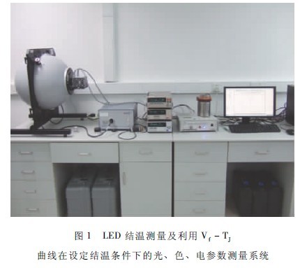
After obtaining the curve of the Vf-TJ of the LED under test, the most important thing is to measure the light, color and electric parameters under the condition of the junction temperature. The detection system is shown in Figure 1. Fix the LED to be tested to the integrating sphere with temperature control/thermostother base, and apply the working current to the LED. After the LED is lit for 15-20 minutes, it will basically switch to the measured current (ie, the front calibration Vf-TJ curve). The measured current) quickly measures the forward voltage Vf of the LED under test in a few milliseconds, and compares it with the Vf corresponding to the set junction temperature value in the Vf - TJ curve. If there is a difference from the target value, the control program will automatically adjust the thermostatic base. The temperature of the socket is such that the forward voltage Vf of the LED reaches the junction voltage corresponding to the target junction temperature value. After a quick measurement of Vf, the device will automatically return to the state where the LED is energized. When the measured LED passes the working current and its junction temperature reaches the target value (ie, reaches the Vf value corresponding to the target junction temperature value) and the heat balance, the system will automatically start the spectrometer to measure the light and color parameters while reading its electrical parameters. .
The most obvious advantage of the above measurement method is that in the actual application of the LED, as long as the LED in the lighting fixture works near the target junction temperature value, the parameters of this method are well simulated, and the measured parameters thereof are also made. It becomes meaningful, and its light, color, and electrical parameters also have good reproducibility of measurement results.
2. 3 LED measurement of junction temperature after entering the lighting fixture
(1) Necessity of junction temperature control and measurement after LED enters lighting fixture
When applied to lighting fixtures, it is generally expected to have a service life of tens of thousands of hours, but to measure the light attenuation and life of LED lighting fixtures, it usually takes more than 300 days (6000h) according to the US DOE LM80 requirements. This is not possible when many projects are tendered and accepted.
As an important parameter to measure the performance of an LED lighting fixture, junction temperature is the core element of reliability measurement of LED lighting fixtures in engineering applications. If the two quantitative indicators of the PN junction temperature of the LED in the lamp and the thermal resistance of the PN junction to a specified point of the heat sink can be accurately measured, it can not only measure the heat dissipation characteristics of the lighting fixture using the LED, but also qualitatively Know the approximate service life of various lighting fixtures using LEDs, and also know what the measured values ​​of LED lighting fixtures and other optical parameters are measured under the junction temperature conditions, and can obtain lighting fixtures. A function of the point on the heat sink of the medium power LED (reference temperature point) as a function of junction temperature, thereby guiding the enterprise to correctly mark the temperature limit of the reference point of the heat sink.
(2) Introduction to measurement methods
At present, the junction temperature of the PN junction of LED at home and abroad can only measure the junction temperature and thermal resistance of a single LED or a single LED module. There is no complete measurement method for the actual junction temperature and thermal resistance of the LED in the lighting fixture. A complete measurement method for the actual operating junction temperature and thermal resistance of LEDs in lighting fixtures.
(1) Vf - TJ curve calibration
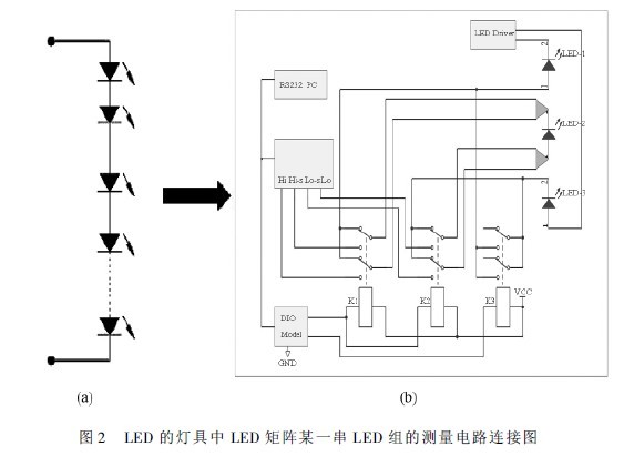
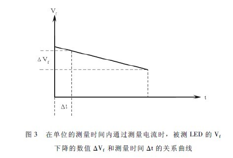
1 As an LED under test in a series of LED groups in the middle of the LED matrix in the lighting fixture, as the LED to be tested, connect the circuit according to Figure 2, the heat sink of this LED (the LED itself is small) A thermocouple is attached to the heat sink. Place the luminaire in a condition of 25 ± 2 °C for 6 to 12 hours (depending on the volume of the tested luminaire to determine the placement time), then apply a measurement current to the LED under test in Figure 2. If, If depending on the LED under test The power can be selected from 2 to 50 mA. The power-on measurement time is from 0. 005 to 2 s. During this period, the forward voltage drop Vf of the LED under test is continuously measured to obtain the curve shown in Figure 3. From this curve, the value ΔVf at which the measured LED in the lighting fixture drops Vf within a unit of measurement time Δt when passing a constant measurement current can be obtained. This value is reserved for the following detection process as a correction amount for measuring the Vf change caused by the current. When the measurement time is less than 3 ms and the measurement current is relatively small, the correction amount may not be introduced.
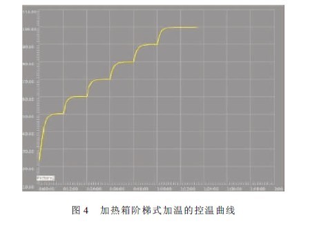
2 Adjust the three 2 knives and 2 throw conversion relays to the measurement position, and put the LED luminaire into a programmable heating special heating box. The heating box adopts PID programming mode and sets the step heating method to the LED luminaire in the cabinet. Heat up. The temperature control curve for stepwise heating is shown in Figure 4. Each step in Figure 4 is divided into a constant temperature period and a temperature rising period. These two time periods can be set separately, and the setting range is any one of 1 to 30 minutes. According to the temperature value reflected by the thermocouple stuck on the heat sink of the LED, and finally measuring the forward voltage drop of the LED under test with the circuit of Figure 2, it indicates that the LED in the fixture has reached the thermal equilibrium of a certain set point temperature. When each constant temperature period is about to end, the forward voltage drop Vf of the LED under test is measured. According to the actual measured time Δt, the correction is ΔVf from Fig. 3. Adding the measured Vf value to ΔVf, and obtaining V'f1 at which D1 is not affected by the measured current, that is, V'f1 = Vf1 + ΔVf, the V'f1 and the temperature measured by the thermocouple T1 is imported into the set computer database. Repeat this step to get a set of corrected values. By automatically importing this set of corrected values ​​into the database, the Vf-TJ curve of the LEDs in the fixture can be generated.
(2) Measurement of LED thermal resistance in lighting fixtures
After taking out the above-mentioned lighting fixture that has been calibrated in the heating box for the Vf-T relationship curve, the LED thermal resistance is measured as follows.
1 Put the lighting fixture into the windshield specified in Appendix D of GB 7000. 1 and arrange the luminaire according to the normal thermal test position. In addition to the thermocouple that has been bonded to the LED D1 under test, it can also be based on The test client requires bonding of thermocouples (either single or multiple thermocouples) at certain points in the heat sink of the LEDs in the luminaire or even at certain points on the luminaire housing. Connect each thermocouple to the thermometer and allow the fixture to stand at 25 ± 1 °C for 8 hours.
2 According to the measured working current value outputted by the LED control device in the lighting fixture to D1, set the test constant current power supply, according to the circuit of Figure 2, D1 is connected to a measured working current, and heated for 1 to 30 minutes, during which the original is used every 1 min. The calibrated measurement current is used to measure Vf of D1, and the corresponding junction temperature value is detected according to the Vf-TJ curve. At the same time, the measured temperature of the thermocouple is monitored, and the measured junction temperature value and the measured temperature value of the monitoring thermocouple are automatically imported. database. When the measured junction temperature of Vf and the temperature measured by the thermocouple reach the maximum difference, the VfR value at this time and the measured temperature value TB of the thermocouple are recorded. The VfR value is passed through the Vf-TJ curve to obtain the instantaneous junction temperature value TfR of the D1. Calculate the thermal resistance of the D1 PN junction to the heat sink or heat sink or even the case according to the thermal resistance RAB = ( TfR - TB) /P formula. In the formula:
TFR————————————————————————————————————————————————————————————————————————————————————————————————————————————————————————————————————————————————————————————————————————————————————————————————————————
TB——— is the measured value of the reference point at the moment measured by the thermocouple when the measured junction temperature of Vf and the measured temperature of the thermocouple reach the maximum difference (the reference point can be a heat sink, or It is a point on the radiator, or it can be a point on the radiator of the lamp housing).
P———The heating power of the measured LED when measuring the thermal resistance is the product of the measured working current and the average value of the forward voltage drop of the measured LED during the junction temperature measurement process.
3 measurement of LED junction temperature in lighting fixtures
Take out the LED lighting fixture from the dedicated heating box. This test can be carried out simultaneously with the thermal test of the lighting fixture. The lighting fixtures using LEDs are still placed in the windshield specified in Appendix D of the GB 7000. 1 standard, and the lighting fixtures are in the normal working position. Adjust the three 2-pole 2-throw conversion relays to the working position, perform the thermal test according to the requirements of 12.4 thermal test in GB7000. 1 standard, and illuminate the LED matrix in the lighting fixture through the LED control device in the lighting fixture. When the LED lighting fixture is in normal working condition, observe the temperature value reflected by the thermocouple stuck on the heat sink of the LED. When the temperature value reaches the thermal balance (the temperature change is less than 1 °C per hour), convert the three 2 knives and 2 throws. The relay is adjusted to the measurement position for 5 consecutive times.
The forward voltage value of the five LEDs tested is measured every tens of milliseconds. The forward voltage drop of the LED under test when the operating current is disconnected is calculated by the computer and special function calculation software, and according to the forward voltage. The relationship between the drop and the junction temperature is used to find the junction temperature of the LED under test in the continuous operation to the thermal balance in the LED lighting fixture. At the same time, the temperature value of the reference point when the lamp is continuously operated to the thermal balance can be obtained.
3 Review and summary
The measurement and control of the LED junction temperature is an indispensable step in the LED lighting field. It combines the LED device with the LED lighting device. By calibrating the Vf-TJ curve of a certain type of LED, and using this curve, it can guide and control the LED to measure the light, color and electric parameters at a predetermined junction temperature, so that the measured values ​​of these parameters of the LED are closer to the actual application state. In addition, the determination of the predetermined junction temperature of the LED also indicates to the LED lighting fixture designer the limits of the thermal control. Similarly, by calibrating the Vf-TJ curve of the LED in the lighting fixture, the LED junction temperature of the lighting fixture under rated conditions can be measured, which not only objectively evaluates the rationality of the heat dissipation design of the LED fixture, but also reveals The reference point temperature on the LED heat sink as a function of junction temperature, and further knowledge of the thermal resistance of the PN junction of the LED to a point on the lighting fixture, thereby guiding the manufacturer of the LED lighting fixture to correctly indicate the reference point temperature limit And in the mass production, it is convenient to basically know the working junction temperature of the LED by measuring the temperature of the reference point.
LED lighting fixtures in normal operation, its thermal characteristics are directly related to light efficiency, light decay and service life, the corresponding indicators are the PN junction temperature and heat dissipation of the LED when operating, if these two indicators do Well, it means that the luminaire is guaranteed in terms of efficiency and service life, just like the inspection of the human body. If the blood test index, color CT examination and blood angiography result are all good, the person's body must be healthy. of. The significance of this test method is to establish a "light test for blood test and color CT and a blood ray analyzer" for LED lighting fixtures and methods thereof.
It is foreseeable that the establishment of this method will be a powerful pusher to guide the design and manufacturing of LED lighting fixtures and to make LED lighting fixture design and production technology go to a higher level.
5V Power Supply, it has multi plug were suitable for many countries. We can meet your specific requirement of the products, like label design. The plug type is US/UK/AU/EU. The material of this product is PC+ABS. All condition of our product is 100% brand new.
Our products built with input/output overvoltage protection, input/output overcurrent protection, over temperature protection, over power protection and short circuit protection. You can send more details of this product, so that we can offer best service to you!
5V Power Supply
5V Power Supply,5V Pc Power Supply,5V Dc Power Supply ,5V Power Supply For Computer
Shenzhen Waweis Technology Co., Ltd. , https://www.waweis.com