![<?echo $_SERVER['SERVER_NAME'];?>](/template/twentyseventeen/skin/images/header.jpg)
Use memory to connect LCD module
The dot-matrix liquid crystal interface is simple and can display various information in a dot-matrix or graphical manner, so it is widely used in various electronic designs. However, its interface must follow certain hardware and timing specifications. Depending on the LCD driver, you may need to issue different commands for control to display data. Moreover, the execution of the command takes a certain amount of time. In the case of a large amount of real-time data in the system, if the liquid crystal display is directly controlled, it may consume too much time, thereby affecting the data processing. Therefore, due to certain needs, different liquid crystal modules must be used, which requires software modification. In order to solve these problems, the article proposes a liquid crystal display module using a memory interface, an MCU (Micro-Controller Unit microprocessor) and related devices are added to the existing dot matrix LCD screen, and the memory is used to interface with an external controller, thereby Solved the problem of unified interface and display speed.
1 System design
1.1 Design ideas
We know that the human eye has the phenomenon of persistence of vision. Images that change every 0.1 second seem to be continuous, and images that only change within 0.1 second are difficult for the human eye to perceive. According to this physical phenomenon, we use a memory interface with an external controller to design an LCD interface module. The external controller writes the data to be displayed directly into the interface memory, and refreshes the LCD display according to the interface. If the refresh rate is more than 10 times per second, the purpose of continuous display can be achieved. Of course, the higher the refresh rate, the more the human eye can feel the continuous and smooth image changes.
1.2 The hardware design adopts the interface between the memory and the external controller and has a unified hardware interface specification. Because the external controller and the MCU in the module need to read and write memory at the same time, the interface memory uses a 2K dual RAM IDT 7132 with BUSY line, the MCU selects the commonly used AT89C51, and the LCD module is a single unit that uses the HITACHI HD61202 LCD controller. 128 × 64 dot matrix LCD powered by 5V. The design of the liquid crystal display module must have strong versatility and can be widely used in various systems. At present, the system is generally a 3V level or 5V level system, so the design of the liquid crystal display module must also be considered for both systems. The hardware block diagram of the LCD module is shown in Figure 1. The external controller writes the data to be displayed into the dual-port RAM, and the MCU continuously scans the memory, performs corresponding processing according to the data in the memory, and constantly refreshes the display on the LCD screen. Considering the timing of LCD and system operation, the AT89C51 single-chip microcomputer runs under a 12MHz clock, and the refresh rate of the design system reaches 18 times per second.
The data, address, and control bus of the external controller are introduced into the LCD module through the connector. Because the input and output of the dual-port RAM IDT7132 is TTL level, and the BUSY signal is an open-drain output, no matter whether it is a 3V or 5V system, the address and control bus can be directly introduced. The data bus is a bidirectional system. If it is directly connected to the dual-port RAM, it may cause damage to the 3V system when the dual-port RAM outputs data. Therefore, a bus driver is designed to use 74LVC245 for bus level conversion. When 74LVC245 is powered by 3V, input 5V voltage signal to realize the interface with 3V and 5V level system.
The BUSY signal of the dual-port RAM is used to indicate that the two ports of the dual-port RAM are accessing the same memory unit at the same time, and at least one port is in the state of writing the unit. The dual-port RAM uses the arbitration logic to validate the BUSY signal that accesses the unit afterwards, and shields the operation of the port until the BUSY signal is not valid until it is not accessed. By detecting the BUSY signal can effectively ensure the safety of memory read and write.
The module uses 27C040 to save 16 × 8 256 ASCII character dot matrix 16 × 16 dot matrix Chinese character library, which is convenient for users to use.
Considering the large current of the LCD backlight, the control of the LCD backlight is added, and the backlight can be switched on and off as needed.
1.3 Software design
The software part involves interface operation, dot matrix operation and liquid crystal operation, etc. Only the relevant parts of the interface are introduced here.
1.3.1 Interface memory allocation
The allocation of interface memory is shown in Table 1.
Table 1 Interface memory allocation table 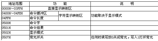
There are 128 × 64 = 8192 points on the LCD screen, and each point is lit or extinguished by one bit in the memory as 0 or 1. The memory allocated from 0000H to 03FFH in the dual-port RAM is used to directly correspond to the points on the screen, and is called the direct display mapping area. In this way, the user only needs to write the dot matrix to be displayed in the designated address in the memory, and can directly display it at the designated position on the screen.
In addition, for the convenience of use, a simple command interface is also designed, and the space of 0400 ~ 0507H is allocated as the memory of the command interface. The specific allocation is shown in Table 1. Among them, the memory of 0400H ~ 04FEH is also used as the character display mapping area. After the display mode is set, the character to be displayed is written to the specified address of the area, and the character can be displayed at the specified position on the screen.
1.3.2 Introduction to Command Interface
The external controller writes the command to the memory of the command interface according to a predetermined format. When the MCU of the display module detects a command, it first reads the command, changes the content of the command word address to 00H, and writes the highest position of the command word to 1 in the command result address, indicating that the command is being executed. After the command is executed, the result of the command execution (the highest bit is specified as 0) is written to the command result address. In this way, the external controller can confirm the current working status of the display module and issue commands by detecting the content of the command word address and the command execution result. The basic command words are shown in Table 2. Of course, command words such as drawing various graphics and filling can be added according to specific applications.
Table 2 Command words and their parameters 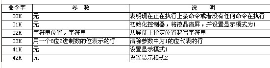
1.3.3 Working mode of interface module
Two display modes are designed: display mode 1 and display mode 2. In display mode 1, the MCU continuously scans the display mapping area and checks the user-written commands in the dual-port RAM. In display mode 2, the MCU continuously monitors the changes in the character display mapping area, converts the characters written by the user into a dot matrix, writes in the direct display mapping area, and then scans the display mapping area for display. At this time, the MCU only executes the change display mode or initialization command. All other commands are ignored. In this way, the external controller does not need to know the specific liquid crystal operation. Operating the liquid crystal is as simple and fast as reading and writing memory. Therefore, the external controller can process a large amount of real-time data and display it in real time.
2 Application examples
The liquid crystal display module has been successfully applied in a set of Bluetooth systems that we designed. The Bluetooth module uses Ericsson Rok 101, and the main controller uses TI's MSP430F149. The animation and all control information transmitted through Bluetooth are displayed on the liquid crystal display module, the effect is very smooth, and meets the design requirements.
The liquid crystal display module proposed in this paper uses memory and an external controller for interface, and has a unified interface specification. The external controller directly writes the content to be displayed into the memory interface provided by the liquid crystal display module to realize the display, without directly performing complicated and time-consuming liquid crystal control and dot matrix processing operations, which is beneficial for the controller to process a large amount of data in real time. At present, similar solutions are adopted for color LCDs with large screens on the market, but they are expensive. For general applications, the liquid crystal display module proposed in this paper has strong versatility, and the increased hardware cost is less than 20% of the purchase of a dot-matrix liquid crystal, so it can be widely used.
The Low Voltage Static Var Generator independently developed by FGI is mainly composed of control panels, energy storage capacitors, reactors, IGBT, inverters, fuses and other devices. The low voltage SVG adopts intelligent algorithm for control, can quickly compensate reactive power, filter harmonics, suppress voltage fluctuation and flicker and can effectively suppress three-phase unbalance, which can well solve the power quality problem of power supply system.
Low Voltage Static Var Generator
Static Compensator,Statcom Power System,Low Voltage Statcom Systems ,Low Voltage Static Var Generator,Var Power,Var Reactive Power
FGI SCIENCE AND TECHNOLOGY CO., LTD , https://www.fgi-tech.com