![<?echo $_SERVER['SERVER_NAME'];?>](/template/twentyseventeen/skin/images/header.jpg)
The future of wireless communications begins with today's MIMO: WiMAX, HSPA + and LTE test challenges
The development trend of the communication market and the underlying voice and data service technologies is to provide higher data rates on the same spectrum to meet the increasing user demand. This article reviews the underlying standards of the multiple input multiple output (MIMO) transmission mechanism, including 802.16e mobile-WiMAX Wave 2, HSPA + and LTE. It involves the MIMO signal generation, modulation quality measurement, channel simulation and beamforming theory used by the majority of engineers when designing products based on multi-radio / antenna technology.
introduction
MIMO technology raises the spectrum efficiency to a whole new level. According to the transmission technology it uses, it can achieve higher data throughput or greater coverage. However, the increase in spectrum efficiency comes at the cost of higher complexity. Conceptually, MIMO technology is very simple: it uses multiple RF carriers to transmit more information, and improves spectrum efficiency by transmitting all signals on the same channel occupying the same bandwidth. For example, a 2 × 2 MIMO radio frequency has two transmitters and two receivers, and a 4 × 4 MIMO radio has 4 transmitters and 4 receivers.
At present, many MIMO systems use a 2 × 2 configuration architecture, but the development of the market will have a larger-scale configuration. WLAN, WiMAX and LTE have adopted a 4 × 4 configuration architecture. At present, the beamforming technology that people are studying is designed to configure a larger-scale radio frequency system in the device to provide users with the most services possible. Currently, 8 × 8 or even 16 × 16 RF configurations are the mainstream in the commercial broadband RF research field.
MIMO theory
The working principle of MIMO is to accurately model the transmission channel and decompose multiple received symbols into a single data stream. To illustrate this principle, we might as well take WLAN 802.11n as an example (as shown in Figure 1). The transmitter sends a known signal in the form of a header. The receiver constructs a channel model based on this, denoted by H. When sending data, the receiver approximates the original vector as much as possible according to the channel model, where it is assumed that the transmission error is represented by a noise vector (n).
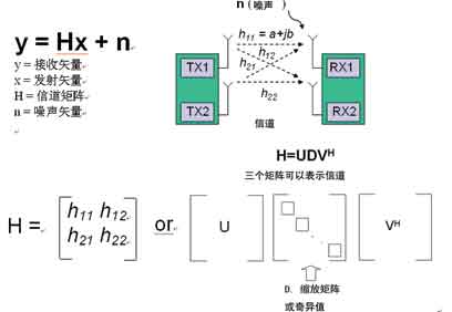
Figure 1 Principle of transmission channel
Although the channel modeling theory is applicable to all MIMO systems, this method is different for different standards. For example, in a system based on WLAN 802.11n, the header information is transmitted on both TX1 and TX2, but a system based on WiMAX 802.16e Wave 2 only transmits the header on the first transmitter. The parsed transmission paths (that is, h11 and h22) are called spatial streams.
There are many situations in which the time alignment of the measurement system distort the signal. For example, reflections from surrounding objects can cause multiple instances of the signal to reach the receiver at different times (multipath). Multipath causes amplitude attenuation and delay in time and phase. In theory, the more the channel distortion of a certain signal, the more difficult it is for the receiver algorithm to parse out the original transmitted signal. If the transmitter or receiver further introduces amplitude, time, and phase errors, we cannot accurately model the channel and cannot effectively resolve the symbols.
In order to ensure that the MIMO measurement is effective and accurate, the measurement equipment used, that is, the signal source (transmitter) and analyzer (receiver), must be phase aligned with their local crystals and time aligned with the reference frequency The D / A and A / D sampling rates are the same to minimize their impact on the channel. Ideally, if the phase error is less than 1 ° and the time alignment error is less than 1ns, then accurate results can be obtained.
System performance modulation quality index: For most traditional digital transmission systems, the key index to measure the modulation quality is the actual received symbol vector (or symbol phase and amplitude distortion) compared with the receiver's expected value. The most commonly used is EVM (error vector amplitude), but different communication standards also have different indicators, such as relative star error (RelaTIve ConstellaTIon Error, RCE). For MIMO systems, the total EVM is also a good measure; by calculating the RMS EVM, the overall modulation quality of each transmitter can be expressed.
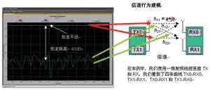
Figure 2 (a) Channel behavior modeling
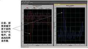
Figure 2 (b) Decay and matrix conditions
Star chart: The star chart is a graphical representation of the received signal quality. MIMO systems have a variety of star charts. The 2 × 2 system has two star maps, representing two parsed spatial streams: h11 and h22. The 4 × 4 system has four star maps. For traditional digital systems, the same quality indicators can be obtained from the star chart, such as phase error, noise, and IQ equalization.
Channel response: Channel response is a key indicator of spatial behavior. In Figure 2 (a), the two transmitters are directly connected to the receiver through a coaxial cable. Two straight lines represent h11 and h22, while two noise-like curves represent h21 and h12. This indicates that the channel isolation is very high. In Figure 2 (b), one of the code streams introduces delay. This causes a large attenuation in the following OFDM symbol.
By using antennas—or achieving more quantitative measurements, the channel simulator—it is possible to derive an accurate channel model. This can help people to use the calibrated receiver as a reference when designing the transmitter to determine whether the signal transmission is reliable under various channel conditions. Similarly, the receiver can be tested using different channel models. These signals can be generated by using arbitrary waveform generators or real-time channel emulators to load certain channel distortions onto standard waveforms.
Since the performance of a MIMO system depends on the behavior of the channel, a variety of different channel models must be used to test the transmitter and receiver—both containing both predefined standards and user-defined models—to ensure that the design Stable performance in this environment. Figure 3 shows a typical configuration. Depending on whether the device under test is a transmitter or a receiver, the Type 2820 Vector Signal Analyzer (VSA) and Type 2920 Vector Signal Generator (VSG) can be replaced by a transmitter or receiver.
Matrix conditions and singular values: Like EVM, matrix condition numbers are also a good indicator of transmitter performance. It actually measures the orthogonality of each spatial stream. For example, if a cable is used to connect the VSA to the transmitter, then the matrix condition should be close to one (ie, 0dB). If this is not the case, then the transmitter may have generated some inter-stream interference, which may be due to a mathematical error in the DSP or a problem with the RF part. Since the matrix condition is the ratio of the largest singular value, the singular value of each code stream can be checked by selecting the singular value measurement. The commonly used measurement method is to monitor the condition number of the matrix until an abnormally large value appears, and then monitor the real singular value to obtain the solution of the matrix. Figure 2 (b) compares the channel response with the matrix conditions.
Stream performance We can analyze the performance of each transmitted stream through a variety of methods.
Measuring for a period of time: Measuring the EVM, amplitude, or frequency error over a period of time can help us find problems related to the time behavior of each RF channel. For example, a glitch in an RF transmitter FPGA may cause periodic errors in the EVM.
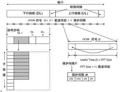
Figure 3 WiMAX unites all
In the parallel symbol transmission mode based on orthogonal frequency division multiplexing, the time increment usually refers to the OFDM symbol period (horizontal axis in FIG. 3), and each time increment includes thousands of symbols. For example, WiMAX (802.16e) can transmit 128 to 2048 symbols per OFDM symbol period. The vertical axis of FIG. 3 is identified as a subchannel (subchannel). These sub-channels are not real physical channels, but groups of parallel symbols transmitted in each OFDM symbol period. Through this kind of symbol diagram, you can define how the 802.16e signal is composed and how it behaves in time.
Modulation quality frequency: Measuring the relationship between EVM or amplitude and frequency can help us identify in-band problems, such as low-level parasitic interference that may be generated by the clock inside the RF.
Beamforming
An important advantage of MIMO—and one of its original uses—is the ability to direct RF energy to specific users through a process called beam forming. Many commercial system standards support MIMO beamforming or closed-loop MIMO. Although the advantage of beamforming is that it can provide users with greater capacity, it increases the complexity of the device because it requires the use of array-type transmitters, receivers and antennas to control the direction and shape of the transmitted signal, which depends on In the channel environment. People use techniques such as channel sounding to model the channel, and then construct the correct code stream phase and amplitude. The test equipment needs to be extended to an 8 × 8 architecture so that it can control the phase and amplitude of each signal source, and construct the required RF transmission pattern based on the calculated channel information.
Conclusion In the process of shifting from analog transmission technology to digital transmission technology, MIMO is one of the most important development trends in commercial radio frequency technology. All next-generation communication standards are based on MIMO, which presents many new challenges for designers of commercial communication equipment. As users require more and more services and more reliable links, MIMO systems will advance around technologies such as beamforming, increasing the number of transmitters, receivers, and antennas in a device .
Balloon Pump Heart,Balloon Inflator Pump,Air Compressor Vacuum Pump,Ac Compressor Vacuum Pump
SHENZHEN SMARTNEWO TECHNOLOGY CO,. LTD , https://www.newopump.com