![<?echo $_SERVER['SERVER_NAME'];?>](/template/twentyseventeen/skin/images/header.jpg)
Calculation of filter parameters based on voltage-type variable frequency speed regulation system
0 Preface
In the voltage-type variable frequency speed control system, the calculation and correct selection of the filter capacitor parameter CF have important and practical significance for ensuring the quality of the system adjustment and reducing the design cost. If the filter capacitor parameter is too large or too small, it not only affects the stability of the system, but the high-frequency signal in the circuit will seriously affect the signal and communication system, and may also cause other systems connected to the same power grid to malfunction.
Therefore, the DC link filter is a very important functional device in the drive system powered by the inverter, and it must be selected correctly and reasonably. However, in actual drive system design, engineers mostly calculate based on empirical formulas, rather than based on the introduction of inverter switching strategies and load characteristics, which makes it difficult to widely change the inverter's switching frequency and pulse width. Therefore, there are major limitations.
Starting from the basic principle of the voltage-type frequency conversion speed control system, the switching strategy of the inverter is introduced, and the change rule of the charging and discharging current of the capacitor CF during the working process is derived. The maximum value, so as to obtain the engineering calculation formula for determining the capacitance parameter. The formula is simple and the physical concept is clear, which is convenient for application in engineering practice.
1 Composition and working principle of voltage-type frequency conversion speed regulation system
The principle diagram of the voltage-type frequency conversion speed regulation system is shown in Figure 1.
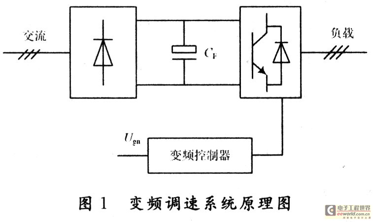
As can be seen from Figure 1, the three-phase AC is converted into DC by bridge rectification, and then filtered by capacitor CF, applied to the inverter bridge composed of GTR1-GTR6 and converted into three-phase AC with adjustable voltage and frequency to provide three-phase asynchronous electric motor. The coordinated control of its voltage and frequency is realized by the inverter controller.
The function of the filter capacitor of this system is:
(1) It plays a filtering role and is used to limit the voltage ripple at the input end of the inverter;
(2) When the asynchronous motor is running in the regenerative braking state, it absorbs the electrical energy returned to the DC link via the inverter bridge.
Obviously, the DC filter link of the system is the filter capacitor CF. The calculation of the filter parameters of the system comes down to the calculation of the capacitance parameter CF.
2 Equivalent circuit of DC link and calculation of charge and discharge current
Based on the following considerations:
(1) During the operation of the inverter, the peak-to-peak value of the voltage across the capacitor should be less than the value specified by the indicator;
(2) The loss of the DC link should be kept to a minimum;
(3) Transient phenomena generated in inverters and induction motors should be sufficiently damped;
(4) The parameters of the DC link should not affect the stability of the entire system.
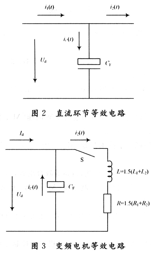
The equivalent circuit of the DC link can be obtained as shown in Figure 2.
From the circuit diagram in Figure 2, if the current i1 (t) ripple is very small, then:
i1 (t) = Id
So you can get:
![]()
Where: iC (t) is the current flowing through CF; Id is the current provided by the DC power supply; i2 (t) is the current to the inverter.
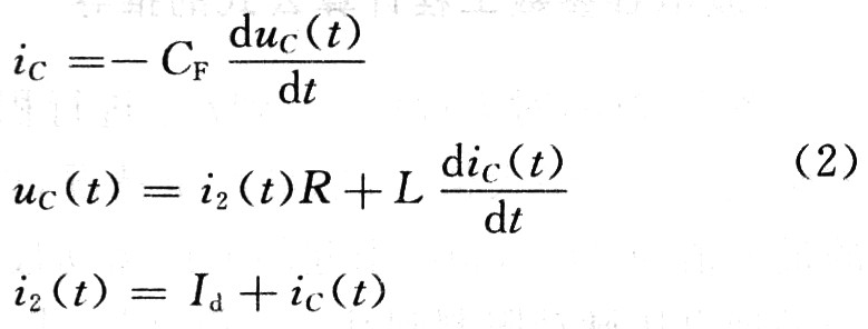
Let the inverter be a six-step wave inverter, and simulate the inverter as a switch. In the case of ignoring the influence of the asynchronous motor rotation potential and the asynchronous motor excitation current, the static model and equivalent circuit of the variable frequency motor can be obtained as shown in Figure 3.
In Figure 3, L1 is the leakage inductance value of each phase stator winding; L2 is the value of each phase rotor winding leakage inductance converted to the stator side; R1 is the resistance value of each phase stator winding; R2 is the resistance value of each phase rotor winding converted to the stator Side value. In this way, when the inverter works normally (that is, S is closed), according to Kirchhoff's voltage law:
The initial conditions are: UC (0) = (1 + K / 2) Ud, iC (0) = 0, i2 (0) = 0. Where K is the ripple coefficient.
From equation (2):
![]()
The characteristic equation of its homogeneous equation is:
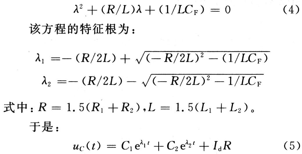
Where: C1 and C2 are constants determined by the initial conditions. When t = 0 (that is, the inverter starts to work):
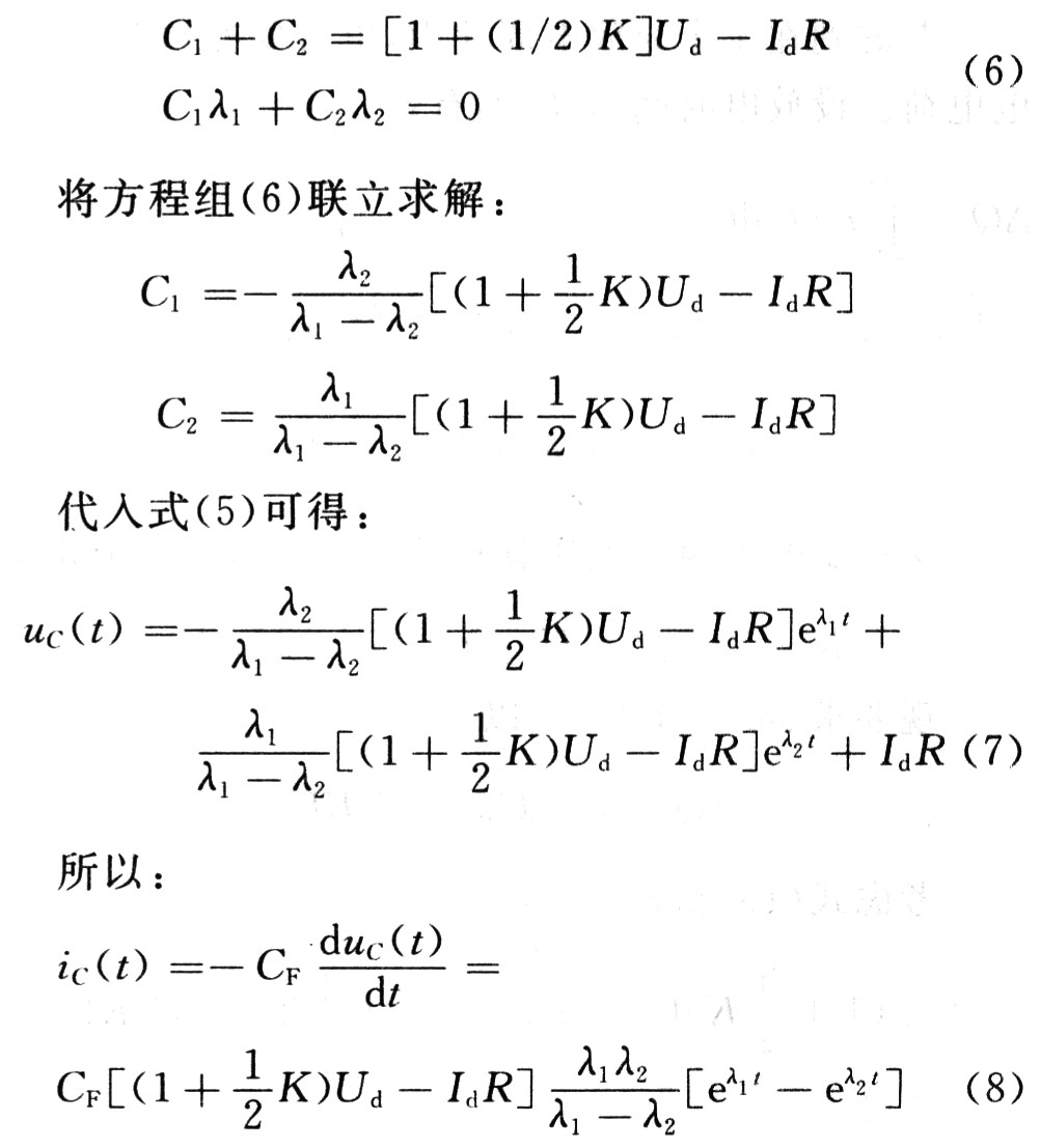
Equations (7) and (8) are the changing rules of the voltage across the capacitor and the current when the capacitor is discharged.
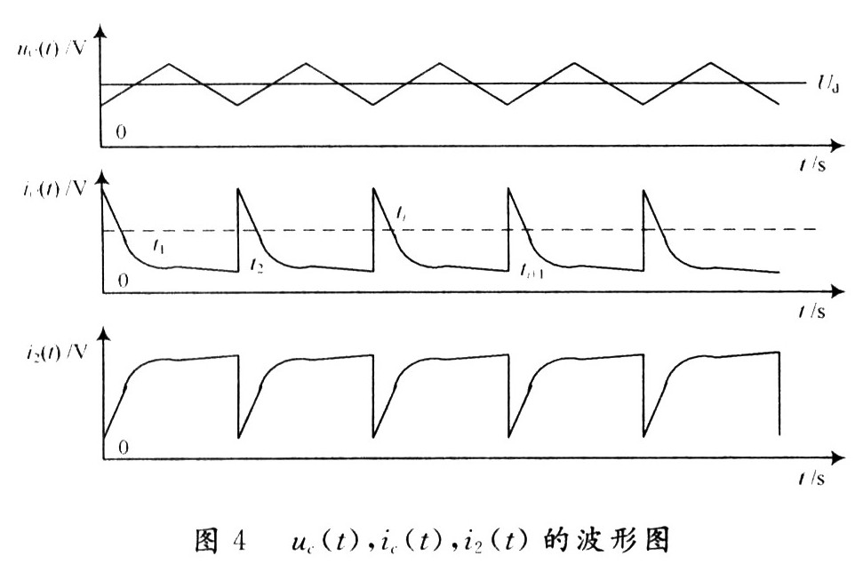
In the same way, the change rule of the voltage at both ends of C during the charging process can be obtained, which is omitted here. So can get uC (t), iC (t), i2 (t) waveform diagram shown in Figure 4.
3 Derivation of filter capacitor parameter engineering calculation formula
Consider equation (8) for iC (t) from TI to TI + 1. By integrating, the maximum value of the charging charge of the capacitor can be obtained. Considering the most serious situation, the maximum value of the stored charge of the capacitor is â–³ QM, and the corresponding maximum value of the voltage ripple caused by it is â–³ UP. Therefore, to limit the voltage ripple to a certain value, it is required to:
CF = â–³ QM ï¼ â–³ UP (9)
Equation (9) is the calculation formula of the filter capacitor parameters of the six-step wave inverter. For the system under study, the inverter is an SPWM inverter. The difference between it and the six-step wave inverter is the different switching frequency, that is, the capacitor charging and discharging time is different, and the output through the inverter It is the AC voltage of the SPWM waveform.
Consider that in a charge-discharge cycle, the charged charge of the capacitor is equal to the discharged charge. Set the discharge time to T, then: 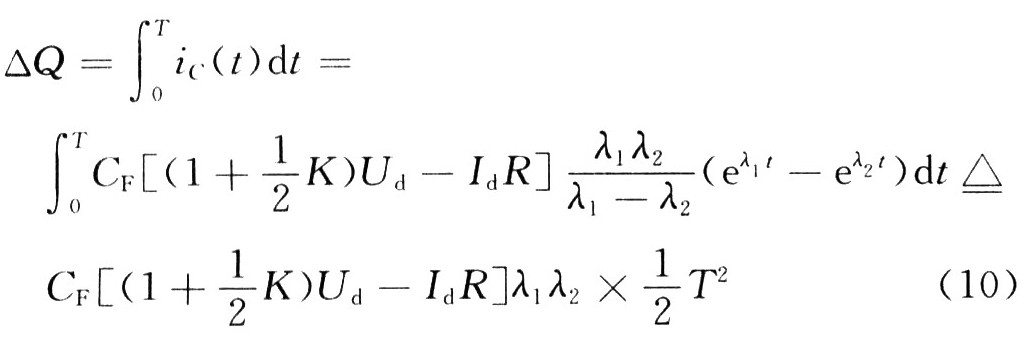
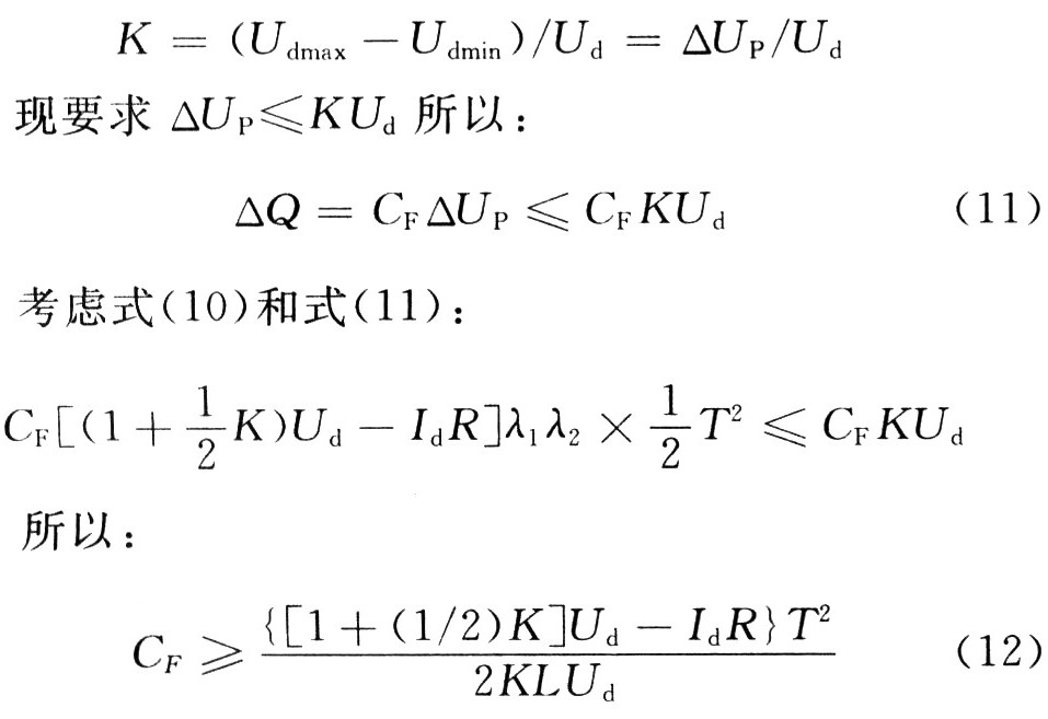
According to the voltage ripple coefficient at both ends of the capacitor (defined according to peak-to-peak value)
Considering that for small and medium power motors, R is small and can be ignored. So equation (12) can be simplified to: ![]()
Equation (13) shows:
(1) The smaller the voltage ripple required by the system, the greater the required filtering capacity;
(2) The higher the frequency of frequency conversion voltage regulation, the capacity of CF can be reduced;
(3) The greater the leakage inductance L of each phase of the motor, the CF capacity required can be reduced.
In summary, it is advisable to consider the most serious situation in the calculation of filter capacitor parameters. The voltage rating of the leakage wave capacitor can be selected according to Ucc≥1.5Ud.
4 Conclusion
The above design ideas were tested in the laboratory JR2-4S 3 kW asynchronous motor frequency conversion speed control system. The parameters of the experimental motor are: Ule = 380 V, Ile = 6.9 V, E2e = 195 V, I2e = 9.5 A, ne = 1 400 rpm, λM = 2. When the voltage ripple coefficient K = 0.02 is required, the theoretical calculation parameter CF = 650μF, and the actual system parameter CF = 600μF, the two basically agree. The experimental results show that the design idea is basically correct. The engineering calculation formula recommended here can be used to calculate the filter capacitor parameters of the small and medium power frequency conversion speed regulation system.
Grow Light Reflector,Outdoor Grow Light Reflector,Outdoor Lamp Cover,Grow Light Lamp Cover
Yangzhou Huadong Can Illuminations Mould Manufactory Co., Ltd. , https://www.light-reflectors.com