![<?echo $_SERVER['SERVER_NAME'];?>](/template/twentyseventeen/skin/images/header.jpg)
Abstract: Based on the LabVIEW virtual instrument technology of National Instruetionals, the vehicle monitoring system was designed and built. The vehicle GPS/Beidou positioning receiving system is used to obtain the positioning information, and the positioning information is transmitted to the monitoring station through GPRS. The monitoring station summarizes the information and returns to each vehicle, and shares and displays the position information of all the vehicles. The monitoring and display software is written in LabVIEW for real-time monitoring of vehicle health. The experimental results show that the system can accurately and effectively monitor and display the running condition of the vehicle.
This article refers to the address: http://
The Intelligent Transportation System (ITS) is the development direction of the future transportation system. It combines the latest information, control and sensing technologies to establish a real-time, accurate and efficient integrated transportation management system. At present, China's intelligent transportation research, water, land and air are mainly focused on improving the overall transportation efficiency and service level, and are used to meet the public service needs of transportation users, navigation and transportation enterprises, and traffic management departments to monitor traffic conditions.
The vehicle onboard monitoring unit is the terminal and network node of the vehicle network. Under normal working conditions, the on-board monitoring unit relies on the public wireless network to directly transmit data information and the like to the regional control center (data center) according to the set route. There is a one-way connection between the vehicle and the data center. That is, the data center can know the information of all the vehicles, but the vehicles cannot know each other's position. In this paper, the vehicle location information in the data center integration area will be broadcasted to all vehicles in the area in real time, so that the location information is shared. In order to ensure that the data of each mobile node can be transmitted in time, the mobile cellular network can be used as a communication carrier to transmit the positioning information provided by the vehicle GPS/BDS positioning receiving system, so that the mobile node information can be effectively transmitted in time.
1 system overall design
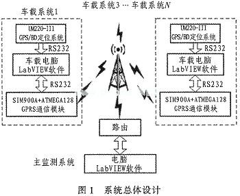
The system structure block diagram is shown in Figure 1, which is divided into two parts: the main monitoring system and the vehicle system. The vehicle system consists of three parts: the vehicle positioning system, the monitoring system, and the communication system. The main monitoring system consists of a monitoring system and a communication system. The in-vehicle system completes the collection of positioning information and transmits it to the main monitoring system via GPRS. The main monitoring system integrates the information sent by all in-vehicle systems over a certain period of time, displayed on the LabVIEW interface and broadcasted to the in-vehicle system. The in-vehicle system then analyzes the collected data and displays it on the LabVIEW interface.
2 vehicle system design
The vehicle-mounted system consists of three parts: the vehicle GPS/BDS (Beidou) positioning and receiving system, the monitoring system, and the information transmission system.
2.1 Vehicle positioning system
The vehicle positioning system uses the UM220-III module with the core star. The UM220-III module is a GPS/BDS dual receiving system module. It uses GNSS multi-system fusion, Kalman filter and other optimization algorithms and the high-sensitivity design of the core-pass Ultra-Sense to maintain excellent capture tracking and reliable continuous positioning results in a variety of complex environments.
GPS/BDS positioning information contains a lot of content. In this system, since only longitude, latitude, and latitude and longitude directions are needed, other information can be set to not be output during setting.
In this paper, the monitoring of the running vehicle, due to the continuous movement of the vehicle, the network environment is constantly changing, so it can provide excellent acquisition and tracking sensitivity under weak signal conditions, and maintain the continuity and reliability of the receiver positioning. Sex is very important. The UM220-III module is connected to the vehicle PC through a serial port (available from USB to serial port) to transmit positioning information to the vehicle PC, and is analyzed and forwarded to the communication module by the vehicle PC.
2.2 Communication system
The vehicle PC will receive the positioning information sent by the UM220-III module, analyze and integrate it by LabVIEW software, and send it to the communication system through another serial port (USB to serial port available). The SIM900A module is controlled by the ATMEGA128 microcontroller and communicates with the main monitoring system via a wireless public network in accordance with the set route.
2.3 Car PC
LabVIEW on the car PC pre-stores certain map information. Therefore, as long as there is positioning information of the car positioning system, you can display its position on the LabVIEW interface. In addition to this, the communication module also receives information from the main monitoring system that includes the location of other vehicles within the area. Therefore, the position of other vehicles will also be displayed on the LabVIEW interface of the car PC.
3 main monitoring system design
The main monitoring system is mainly composed of a PC with a fixed IP. The PC relies on a public wireless network to receive information from the in-vehicle communication system, and LabVIEW implements its monitoring and communication functions.
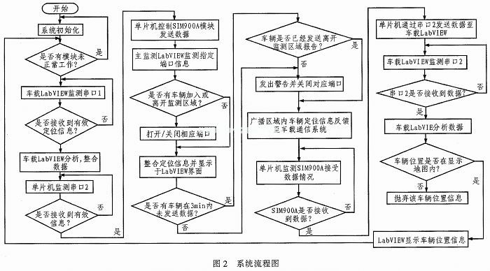
The specific system flow chart is shown in Figure 2, in which the car PC serial port 1 is connected to the UM220-III module, and the serial port 2 is connected to the communication module. Each port communication module must specify a port when communicating with the main monitoring system.
4 Software Design Section
4.1 LabVIEW Serial Program
The serial port is the most classic traditional communication interface of the computer, and it is also the most widely used interface. LabVIEW also integrates the serial communication function. Therefore, the wired communication interfaces in the text all use serial port or USB to serial port.
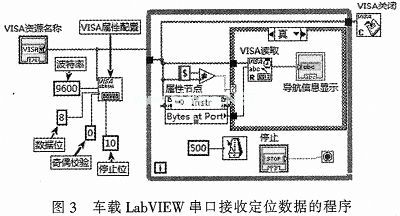
LabVIEW's serial communication function palette contains the functional modules commonly used in serial communication. This system mainly uses VISA Resource Name, VISA Configuration Function (Configure Serial Port), VISA Read Function (Read) and VISA Close Function (Close). The VISA configuration function is mainly used to configure the initialization of the serial port. The serial communication program used in this system has a baud rate of 9600, a data bit of 8 bits, a parity parity bit of 0 bits, and a stop bit of 1 bit.
In this system, because the number of vehicles is uncertain, and the time when each vehicle sends data to the LabVIEW software of the main monitoring system is different, the serial port in the program receives the data by passive receiving. The data bit is set to 8 bits, ie the program is set to
Each time I read 1 byte of data from the serial port, when the program determines that the byte is valid data (frame header "$"), it starts reading, accessing, splitting, calculating, converting, etc. the subsequent data. A series of processing, at the end of the program, use the VISA shutdown function to release the occupied serial port resources.
The program for monitoring the serial port receiving data by the LabVIEW software installed on the car PC is shown in Figure 3.
4.2 LabVIEW UDP Communication
The in-vehicle system and the main monitoring system rely on the wireless public network for communication. Specific to the LabVIEW software, it utilizes its UDP communication function.
TCP/IP (Transmission Control Protocol, Internet Protocol) is the standard for network communication. It is by far the most widely used protocol. UDP mode is connectionless communication, which uses broadcast to publish data. It is especially suitable for point-to-multipoint communication, and its response speed is fast, which is suitable for the situation in the text.
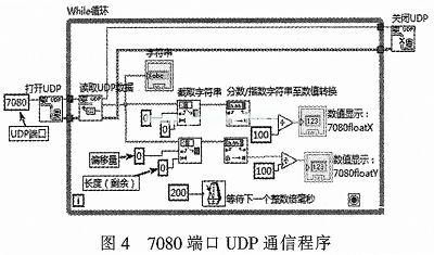
The "write UDP" function needs to specify the computer and the sending port. The IP/loopback IP of the computer as the main monitoring system PC is specified (default, no configuration is required), and the sending port is the port specified in the ATMEGA128 microcontroller program of the in-vehicle communication system. Take "7080" port as an example, the UDP communication program is shown in Figure 4.
4.3 In-vehicle System LabVIEW Design
There are two main functions of LabVIEW in the vehicle system: 1) receiving positioning information from its own positioning system, analyzing and integrating it, and displaying it on the interface in real time; 2) receiving other vehicle positioning information sent by the main monitoring system to determine its position Whether it is within the map of the location of the vehicle, if it is, it will be displayed in real time; if not, discard the information.
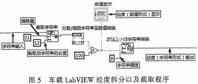
In-vehicle LabVIEW should integrate the positioning data into two parts: longitude and latitude. The two VI programs are basically similar. In this paper, the longitude splitting and intercepting programs are listed, as shown in Figure 5. In the VI subroutine of the LabVIEW, it is relatively simple to judge whether other vehicles are within the map range displayed by the vehicle, but the data processing and comparison size are not listed here.
4.4 Main Monitoring System LabVIEW Design
The SIM900A module of the vehicle communication system in this system is controlled by ATMEGA128 single chip microcomputer. When it sends data, you need to select the port of the receiving end. Therefore, the LabVIEW of the main monitoring system can clearly distinguish which in-vehicle system each positioning information belongs to.
The LabVIEW of the main monitoring system needs to monitor the operation of all vehicles. Its main functions are threefold: 1) display the position information of all vehicles in real time; 2) display the recent route map of all vehicles when necessary; 3) can The operation of a vehicle is shown separately.
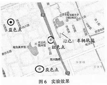
The main monitoring system is similar to the in-vehicle system program, the main difference being that the vehicle's recent road map can be displayed. Just add an "accept buffer" to store the vehicle's recent location information. Figure 6 shows a portion of the on-board LabVIEW software interface display. Among them, the blue, red, and gray three points are other vehicles in the area, and the green is the recent driving route map of the vehicle. The experiment in this paper is carried out on the campus of Shanghai Jiaotong University. In order to facilitate the experiment, the number of onboard systems is 4, and in actual use, it can be increased according to the situation.
5 Conclusion
This system uses NI LabVIEW as the main monitoring and display software, and realizes the sharing and monitoring of vehicle location information in the vehicle on the vehicle software and the main monitoring software. Both the on-board system and the main monitoring system can realize real-time acquisition, processing, storage and display of positioning data by operating only one interface. This greatly simplifies the operation.
The system described in the paper has the characteristics of low cost, simple operation, high degree of automation, scalability and portability. On this basis, the system can be further improved in the future to make it more practical. For example, an alarm, etc., can be installed on the vehicle to transmit an alarm to the monitoring center or to issue an early warning message to other vehicles in the area. Or design the input of text information/voice information on the vehicle LabVIEW program, so that the vehicle can communicate directly with the vehicle in the monitoring center or area. In addition, with the improvement of residents' living standards, the use of vehicles will be more frequent, and the connection between vehicles is also more important. It is not convenient to call or use other communication tools when driving. The method proposed in this paper can also provide some reference for this research.
Bed Vacuum Cleaner : With the beautiful design, this mini Portable Vacuum Cleaner will be good scenery in the house. Small body and high efficiency, the Handheld Vacuum Cleaner is very easy for using and for storage in a small space. You don`t need to worry where to store it. For cleaning the small dust or hair and other small appliances, it will be a very good helper. Of course, this wireless vacuum cleaner also has other functions to remove the dust on table, computer, car, etc. Choose it and you will like it.
Rechargeable Handheld Vacuum cleaner: This Mini Vacuum Cleaner can be used for cleaning hidden dirty of notebook keyboard, printer, pet food, office, kitchen table, or other small household appliances.
Car mini vacuum cleaner: This Usb Vacuum cleaner can be used for cleaning car vent, dashboard, storage cabinet, sand, dust, paper, food debris, and so on.
Rechargeable wireless vacuum cleaner: this vacuum cleaner power supplied by usb port, which is very easy and convenient to use and store.
Easy to use: this mini vacuum cleaners` filter can be washed by water. Just open the dust pot and take it out, then wash it clean and use it again after it dry.
Bed Vacuum Cleaner
Bed Cleaning Robot,Vacuum Cleaner For Bed Bugs,Bed Bath And Beyond Shark Vacuum,Bed Bath And Beyond Vacuum Cleaners
SHENZHEN HONK ELECTRONIC CO., LTD , https://www.honktech.com