![<?echo $_SERVER['SERVER_NAME'];?>](/template/twentyseventeen/skin/images/header.jpg)
Intelligent monitoring robot is a frontier topic in robot application engineering in recent years. Intelligent detection trolley is a kind of intelligent walking robot. The intelligent monitoring machine car is designed for the above situation, based on the principle of reducing costs, based on most of the current intelligent robots. The car features temperature and humidity and environmental monitoring, wireless communication, obstacle avoidance and wireless remote control. Compared with the existing similar designs, this intelligent monitoring machine car has the advantages of high cost performance, convenient operation, good reliability and low power consumption.
1 system structure and hardware design
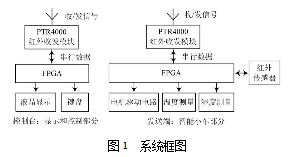
The entire system consists of the sender (smart car part) and the receiver (console: control and display part), as shown in Figure 1. The system consists of sensor system, power and steering system, CCD image sensor module, LCD display, temperature and humidity measurement circuit and power supply system. The control core of the whole system is based on two EP2C20F484 of Altera Corporation, and Quartus II and Altera Corporation. Completed in the SoPC Builder development environment. Add the required peripheral modules according to the system hardware structure and generate the Nios II CPU.
1.1 Power supply system
The car is equipped with two rechargeable batteries, which provide energy for the FPGA development board (FPGA control circuit) and the car movement, and the battery is placed on the bottom of the car.
1.2 Sensor System
The system uses six infrared radiation sensors to detect the sensor signals through the Nios IICPU configured by the FPGA to realize the function of the vehicle to avoid obstacles. The diffuse reflection type infrared radiation sensor, also called photoelectric switch, is a sensor integrating the transmitter and the receiver, and is mostly used for detecting obstacles. The principle is that the modulated infrared beam radiated by the photoelectric switch is reflected back by the detected object, and the infrared ray is received by the synchronous strobe, and the circuit is driven by the electronic switch circuit to detect the presence or absence of the object. A diffuse reflective photoelectric switch is the preferred detection mode when the surface of the object being detected is bright or its reflectivity is extremely high. This circuit module is small in size and the signal is easily converted to a standard level.
1.3 Power and steering system
This car has two motors for the left and right wheels and a turtle machine. The drive circuit adopts the high-power DC motor drive chip L298 of CT Microelecttonics, which supports up to 50 V voltage and the maximum current is 5 A. It meets the requirements of high-power motors, and the peripheral circuit is simple. At the same time, because the chip is a two-way structure, respectively Controlling the left and right motors increases the reliability of the circuit and reduces complexity. The motor control uses PWM pulse width modulation to control the forward speed of the car. The control word is written by the Nios II CPU to obtain PWM drive signals with different duty ratios. The PWM signals are sent to the control terminal of the motor drive chip to adjust the speed.
1.4 car automatic obstacle avoidance system
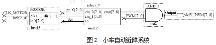
The car automatic obstacle avoidance system uses the Verilog HDL language to write the drive circuit. The module (see MOTOR in Figure 2) is connected to a data selector (see select_2 in Figure 2) to switch between automatic obstacle avoidance and manual remote control. When the SEL pin of the Nios II CPU on the car outputs a low level, the data selector will use the output of the module as the motor's control command. The advantage of this design is that the design is responsive, does not require the participation of the Nios II CPU, improves the CPU processing humidity, temperature data and controls the efficiency of the wireless module to send and receive data. The working principle of the logic circuit is to control the working state of the motor through logic judgment according to the data sent back by the infrared sensor.
1.5 Manual control of the car
The conversion between the manual control and automatic obstacle avoidance of the trolley is controlled by a data selector. When the SEL pin of the Nios II CPU of the trolley outputs a high level, the data selector will use the command sent by the wireless module as the control command of the motor. Achieve wireless control of the car.
1.6 Temperature and humidity measurement
In the temperature measurement system, the new digital temperature sensor DS18B20 with strong anti-interference ability is adopted. In the system design, the pins 1 and 3 of the DS18B20 are respectively connected to the GND and +3.3 V pins of the FPGA board, and the 2 pins are connected. FPGA I/O pin, transmission control and data signals. The maximum available 12 bits of the DS18B20 are temperature values, and the highest 5 bits are sign bits.
HS1101 humidity sensor with fast response, wide working temperature range (-40~+100°C), large measuring range (0%~100%RH), high reliability, good stability, low power consumption, simple peripheral circuit Etc.
The working principle is as follows: The HS1101 sensor and TLC555 form a multivibrator, and the internal capacitance of the HS1101 sensor changes with the change of humidity, so that the output frequency changes. Writing a VHDL program In the FPGA, a frequency meter can accurately measure the frequency value, and the humidity value can be obtained by the relationship between the output frequency and the humidity.
1.7 Wireless Transceiver System
The system adopts PTR4000 wireless embedded module, the working frequency is 2.4 GHz, the maximum working speed is up to 1 Mb/s, efficient GMSK modulation, and CRC error detection. It has the advantages of low power consumption, strong anti-interference ability and small size. There are three main modes of operation: configuration mode, ShockBurst transmission mode, and ShockBurst reception mode.
2 software design and debugging
C language programming with Nios II. The NiosII Integrated Development Environment (IDE) is the basic software development tool for the NlosII family of embedded processors. All software development tasks can be done under Nios IIIDE, including editing, compiling, and debugging programs. NiosIIIDE is based on the open, extensible Eclipse IDE project and EclipseC/C++ Development Tools (CDT) project. NiosIIIDE provides a graphical user interface for the GCC compiler to support standard C. The NiosIIIDE build environment automatically generates a makefile based on the user-specific system configuration (SoPC files generated by SoPC Builder), which facilitates program development.
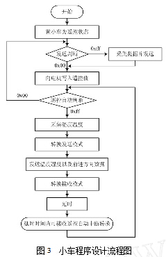
NiosIIIDE includes a powerful software debugger based on the GNU debugger - GDB. After the software code is written, the code can be simulated and debugged. The Nios-II IDE provides a convenient way to program flash memory. Any Common Flash Interface (CFI)-compatible flash device connected to the FPGA can be sintered by the NiosIIIDE flash programmer. For this design and application, a system control program and an LCD display program have been written. The flow chart is shown in Figure 3.
3 system debugging
The car system needs to test whether it can accurately receive the commands sent by the console and control the movement or stop of the car, as well as forward, backward, left and right steering. Also test whether the master can accurately receive the temperature and humidity information collected by the car, and whether it can be displayed correctly. After many tests, it was found that the system program is a mode that uses the transmission and reception cycle conversion. In order to allow the two systems to receive the information sent by the other party, the remote control and the automatic part of the car are simply differentiated. In the automatic case, the console is the main receiving end, and the car is the main sending end. In general, the car sends data to the console, and when it needs automatic to remote conversion, it performs automatic to remote control by interrupting within the delay time. In the remote control state, the console is the main transmitting end, and the trolley is the receiving end. Under normal circumstances, the console sends the trolley traveling command to the trolley. When the data needs to be collected, the temperature and humidity collection buttons are used to transmit and receive the conversion of the trolley. The car issues a data acquisition command and then switches to receive mode again. After doing this, the software part of the car and the console is clear, and the travel of the car and the collection and display data can be performed in real time.
The humidity measurement system needs to test whether the frequency value can be accurately output. Using the circuit recommended in the manual of the chip LM555, the frequency of the output is not accurate due to the error of the component. After comparison with the standard hygrometer, the parameter is adjusted and approximated by a straight line. The resulting frequency value error is in the hertz. (The frequency range is 6 008 to 7 314 Hz), and a very accurate humidity value is obtained through the budget. When starting to find the humidity value, the method of solving the cubic equation is used. Because of the large amount of calculation, it will have a great influence on the travel of the car. Later, at the car end, only the frequency value collected by the car is transmitted to the main control terminal through the infrared antenna. And the original car automatic obstacle avoidance is changed from Nios IICPU control to hardware module written by Verilog, and finally the humidity value is calculated in the console. This change not only reduces the workload of the Nios II CPU of the car, but also makes it run smoothly because the automatic obstacle avoidance of the car is controlled by a separate Verilog module.
For wireless transceiver systems, test their reliability and the accuracy of the information sent or received. The test method is to separately design a soft core to download to the SoPC, and write a program to test whether the configuration control word is correctly written, whether it can receive or send in the ShockBurst mode. The problem is to grasp the timing of each mode of the antenna. The program written at the beginning can't write the configuration word correctly, repeatedly debug, and use the digital oscilloscope to observe the instantaneous process of writing the configuration word and the time of each delay. Finally, the test is successful, and The status of the transmission or reception is displayed by the LED, and the LED is flashed every time a data packet is sent or received.
4 Conclusion
This design is based on FPGA embedded NiosII soft core processor, supplemented by necessary peripheral circuits to form a highly integrated system-on-chip. In addition, the flexible configuration of the SoPC system makes it possible to extend off-chip memory and multiple outputs based on this system. The designed car has strong obstacle avoidance capability, and can be conveniently controlled by the receiving end. The temperature and humidity collection achieves high precision and can realize dynamic display. The effective range of the wireless transceiver module is the farthest. Up to 300 m, it can be used in harsh environments, and can be used for field testing of temperature and humidity.
TECHNOLOGY
WHAT IS AN Air Purifier?
Breathing clean air is very important.
It is scientifically proven that the air in our homes contains allergens(pollen ,mites ,moulds ,etc ).
noxious substance, bacteria viruses and suspended smells.
We have the solution for it!
Esp Air Purifier washable Air Cleaner
12 hour settings,allows you to program the unit to automatically shut off for convenience and energy efficiency
Permanent,washable filter,reduces dust,allergens and impurities in the air for a fresh,clean living environment.
A clean filter indicator alerts you when the filter needs to be cleaned
Sleep mode
Negative ion
Golbal Patent Technology
Our new technology is still ESP technology,but with non-metallic electrodes,it uses the principle of higher resitivity alloy negative electrode junction plastic ionized air.The higher resistivity is relatively high,the distance between the poles can do much smaller without causing breakdown;with the same volume,it can provide considerable absorption area to increase CADR.
Office Air Purifier,Washable Filter Air Purifier,Electrostatic Air Cleaner For Home,Washable Air Purifier For Home
Ningbo Zhe Kai Electric Appliance Co.,Ltd , https://www.cnairpurifiers.com